Varistor
Voltage-dependent resistor

Libraries:
Simscape /
Electrical /
Passive
Description
The Varistor block represents a voltage-dependent resistor (VDR). This component is also commonly known as a metal-oxide varistor (MOV). The block exhibits high resistance at low voltages and low resistance at high voltages.
You can protect parts of an electrical circuit from high-voltage surges by placing this block in parallel with them. When a surge occurs, the resistance of the varistor drops significantly, causing the current to be shunted through the varistor rather than through the circuit.
Use the Parameterization parameter to choose between two
different behaviors for this block. The Linear option focuses
on the on- and off-states of the varistor and uses a linear relationship between current
and voltage in both regions. The Power-law option uses an
exponential relationship between current and voltage in the initial on-state. This
option also adds a third, linear region at higher voltages.
Linear Parameterization
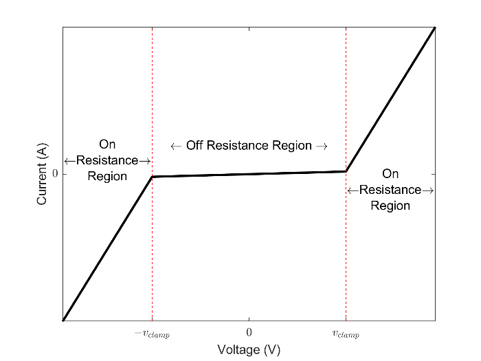
This parameterization option separates the voltage-current relationship into two linear regions:
Off-region — resistance is high and current increases slowly with increasing voltage.
On-region — resistance is low and current increases rapidly with increasing voltage.
This figure shows the voltage-current relationship across the on- and off-regions.
Use linear parameterization in one of these scenarios:
You are modeling voltage surges close to the threshold voltage
You expect your varistor to behave linearly in all regions
The voltage-current relationship for the linear varistor is:
where:
vvaristor and ivaristor are the varistor voltage and current, respectively.
vclamp is the threshold voltage that separates the two regions of operation. Set this value using the Clamping voltage parameter.
Ron and Roff are the resistances in the on- and off-regions. Set these values using the On resistance and Off resistance, respectively.
c1 is a constant used to enforce current continuity between the two regions:
Power-Law Parameterization
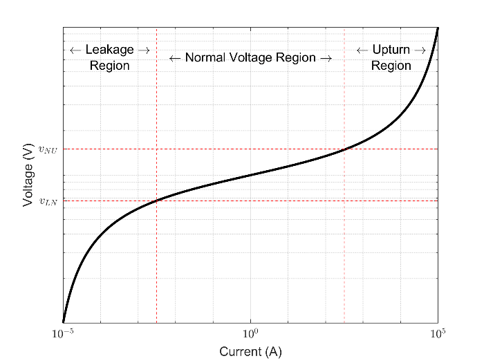
This parameterization option separates the voltage-current relationship into three regions:
Leakage region — Resistance is high and current increases slowly with increasing voltage.
Normal region — Resistance decreases exponentially with increasing voltage.
Upturn region — Resistance is low and current increases rapidly with increasing voltage.
This figure shows the three regions of operation in log-log-scale.
Use power-law parameterization in one of these scenarios:
You are modeling voltage surges across a large range of voltages
You expect your varistor to behave exponentially in the first on-region
The voltage-current relationship for the power-law varistor is:
where:
vvaristor and ivaristor are the varistor voltage and current, respectively.
α is the power-law exponent which determines the rate of current increase with voltage increase in the normal region. Set this value using the Normal-mode power-law exponent parameter.
vLN and the vNU are the threshold voltages corresponding to the leakage-normal and normal-upturn transition points. Set these values using the Leakage to normal voltage transition and Normal to upturn voltage transition parameters, respectively.
RL and RU are the resistances in the leakage- and upturn-regions. Set these values using the Leakage-mode resistance and Upturn-mode resistance parameters, respectively.
k, c1, and c2 are constants used to enforce current continuity between the regions:
and
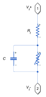
Equivalent Circuit
In addition to the varistor equations, you can also specify a constant terminal resistance Rt and device capacitance C. This figure shows the equivalent circuit for the varistor in either parameterization mode.
Examples
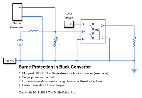
Surge Protection in Buck Converter
How a varistor may be applied to a buck converter in order to protect the switching MOSFETs from over-voltages due to a differential surge.
Ports
Conserving
Parameters
Extended Capabilities
Version History
Introduced in R2018a
See Also
Variable Resistor | Diffusion Resistor | Thermal Resistor | Resistor