BLDC Current Controller with PWM Generation
Discrete-time brushless DC Motor current PI controller with pulse width modulation generation
Libraries:
Simscape /
Electrical /
Control /
BLDC Control
Description
The BLDC Current Controller with PWM Generation block generates a pulse width modulation (PWM) signal and controls current in a brushless DC motor. The controller uses this algorithm.
Equations
The BLDC Current Controller with PWM Generation produces the duty cycle for a BLDC block by implementing proportional-integral (PI) current control using this equation
where:
D is the duty cycle.
Kp is the proportional gain.
Ki is the integral gain.
Ts is the time period.
Is_ref is the reference current.
Is is the measured current.
Gzc is the zero cancellation polynomial.
The closed-loop transfer function for the PI control algorithm yields a zero that can be cancelled by using zero-cancellation block in the feedforward path. The zero-cancellation transfer function in discrete-time is:
The block obtains control signals for the three phases by multiplying the duty cycle by the commutation signals. The resulting three control signals are normalized over the interval [-1, 1].
The PWM generator outputs a 1 when the value of the control signal is greater than the carrier counter value. Otherwise, the PWM generator outputs a 0.
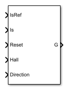
Ports
Input
Output
Parameters
References
[1] Stirban, A., I. Boldea, and G. D. Andreescu. "Motion-Sensorless Control of BLDC-PM Motor With Offline FEM-Information-Assisted Position and Speed Observer." IEEE Transactions on Industry Applications. 48, no. 6 (2012): 1950-1958.
Extended Capabilities
Version History
Introduced in R2018a