Ideal Switch
(To be removed) Implement ideal switch device
The Specialized Power Systems library will be removed in R2026a. Use the Simscape™ Electrical™ blocks and functions instead. For more information on updating your models, see Upgrade Specialized Power System Models to use Simscape Electrical Blocks.
Libraries:
Simscape /
Electrical /
Specialized Power Systems /
Power Electronics
Description
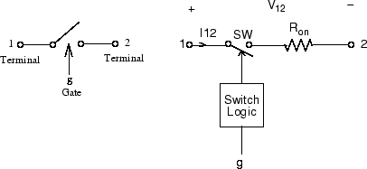
The Ideal Switch block does not correspond to a particular physical device. When used with appropriate switching logic, it can be used to model simplified semiconductor devices such as a GTO or a MOSFET, or even a power circuit breaker with current chopping. The switch is simulated as a resistor Ron in series with a switch controlled by a logical gate signal g.

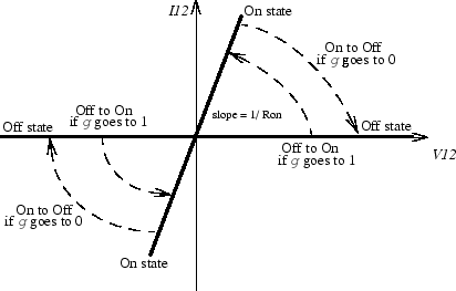
The Ideal Switch block is fully controlled by the gate signal (g > 0 or g = 0). It has the following characteristics:
Blocks any forward or reverse applied voltage with 0 current flow when g = 0
Conducts any bidirectional current with quasi-zero voltage drop when g > 0
Switches instantaneously between on and off states when triggered
The Ideal Switch block turns on when a positive signal is present at the gate input (g > 0). It turns off when the gate signal equals 0 (g = 0).
The Ideal Switch block also contains a series Rs-Cs snubber circuit that can be connected in parallel with the ideal switch (between nodes 1 and 2).

Assumptions and Limitations
The Ideal Switch block is modeled as a current source. It cannot be connected in series with an inductor, a current source, or an open circuit, unless its snubber circuit is in use.
Ports
Input
Output
Conserving
Parameters
References
[1] Mohan, N., T.M. Undeland, and W.P. Robbins, Power Electronics: Converters, Applications, and Design, John Wiley & Sons, Inc., New York, 1995.
Extended Capabilities
Version History
Introduced before R2006a