Model a Rigid Body in MATLAB
R2026bThis example shows how to create a rigid body with MATLAB® classes of Simscape™ Multibody™.
Construct a link for a four-bar mechanism.
Define geometry, mass distribution, and visual properties for the link.
Add frames and connectors to the link to attach other components.
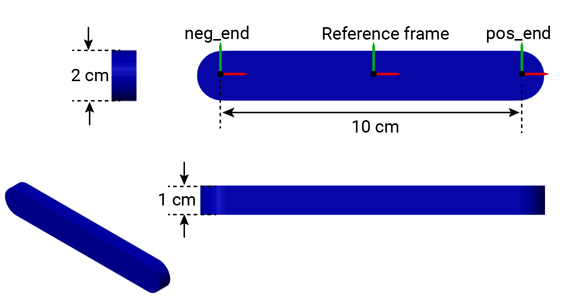
The link has a rectangular cross-section with rounded ends and two frame connectors at each end.
To avoid typing the namespace name for the classes, use the import function.
import simscape.Value simscape.op.* simscape.multibody.*;
Create a Rigid Body Object
Create a simscape.multibody.RigidBody object to represent the link. A RigidBody object is a hierarchical container that can contain multiple rigidly connected frames and component objects. In this example, the RigidBody object includes one rigid solid with two end frame connectors.
To create a RigidBody object named link, use the simscape.multibody.RigidBody class.
link = RigidBody
link =
  RigidBody:

  No connectors.

  Frames:

  Frame        Parent  Source  Connector?
  ___________  ______  ______  __________

  "reference"  --      --      No

  No components.

  RigidBody with properties:

         FrameNames: "reference"
     ComponentNames: [0×1 string]
    FrameConnectors: [0×1 string]
The object starts with one reference frame and zero connectors.
Construct the Link Body
To construct the link body, use the simscape.multibody.UniformSolid class. Specify geometry, mass distribution, and visual properties. The link has a length of 10 cm, a width of 2 cm, and a height of 1 cm. The length aligns with the x-axis of the local reference frame.
To define the dimensions, use simscape.Value objects:
length = Value(10,"cm");
width = Value(2,"cm");
height = Value(1,"cm");
The link has a rectangular cross-section with rounded ends. To define the geometry of the body, use the simscape.multibody.GeneralExtrusion class with a custom cross-section specified by the roundedRect function:
geometry = GeneralExtrusion(roundedRect(length,width),height);
function cross_section = roundedRect(length,width)
angles = (-90:10:+90)' * pi/180;
semi = width/2 * [cos(angles) sin(angles)] + repmat([length/2 0], size(angles));
cross_section = [semi; -semi];
end
To specify color for the link and density for the body, use the simscape.multibody.SimpleVisualProperties and UniformSolid classes:
color = SimpleVisualProperties([0 0 1]);
sg = SurfaceGraphic(color);
geometry.SurfaceGraphic = sg;
density = Value(2700,"kg/m^3");
body = UniformSolid(geometry,density);
To add the body to the reference frame of the link object, use the addComponent method.
addComponent(link,"Body","reference",body);
Add Frames and Connectors
Next, add frames and connectors to the RigidBody object. RigidBody objects use frame connectors to connect to other frames or components.
The link object has a reference frame located at the centroid of the body, which serves as the root of its tree structure. When adding new frames to the link object, you must position them relative to the reference frame by using the simscape.multibody.RigidTransform class. Ensure each frame has a unique name.
Use the addFrame method to add a frame to each end of the link, and name them neg_end and pos_end. The axis of the link is along the x-axis of the local reference frame.
offset = length/2;
addFrame(link,"neg_end","reference",RigidTransform(StandardAxisTranslation(offset, "-X")));
addFrame(link,"pos_end","reference",RigidTransform(StandardAxisTranslation(offset, "+X")));
To connect to other frames or components, the frames must function as frame connectors. However, a newly created RigidBody object initially has no connectors. To expose a frame as a frame connector, use the addConnector method.
addConnector(link,"neg_end");
addConnector(link,"pos_end");
To view the structure tree of the link object, use the plotStructure method.
plotStructure(link);
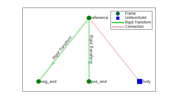
The plot shows that the link object has one solid body and three frames.
See Also
simscape.multibody.GeneralSolid | simscape.multibody.UniformSolid | simscape.multibody.RigidBody

