Simulink Real-Time
Generate real-time applications for simulations that run on a target computer and interface with I/O devices in the target computer
Since R2020b
Description
Use the Simulink Real-Time app to configure a model to build and run real-time applications on a target computer. The app configures the model to use the Simulink Real-Time code generation target and other configuration parameters for code generation. When you open the app, a Real-Time tab is added to the toolstrip. The Real-Time tab represents groups of tasks in the Simulink Real-Time workflow.
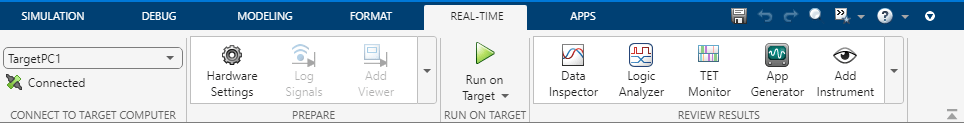
After you use the app to configure the model for Simulink Real-Time, you can perform these and more tasks from the Real-Time tab in the Simulink Editor.
Use the actions in the Connect to Target Computer section to select and connect to a target computer.
UI Control | Description |
|---|---|
From the target computers list on the Real-Time tab,
select the target computer to
which you want to connect. For more information, see the |
Use the actions in the Prepare section to configure the model and tune parameters.
UI Control | Description |
|---|---|
| Use the Hardware Settings button to configure model to run on target computer. The Configuration Parameters dialog box opens. |
| Use the Log Signals button to send signal to the Simulation Data Inspector and workspace. Select one or more signals before using this button. |
| Use the Add Viewer button to add a display of the selected signals. Select one or more signals before using this button. |
| Use the Test Point button to allocate memory and make signals observable when using a Floating Scope. Select one or more signals before using this button. |
| Use the Signal Table button to show a table that manages signal logging and viewing. The Signal Table tab opens at the bottom of the Simulink Editor. |
| Use the Configure Logging button to configure signal logging. The Data Inport/Export tab of the Configuration Parameters dialog box opens. |
| Use the SLRT Explorer button to open the Simulink Real-Time Explorer app. For more information, see Simulink Real-Time Explorer. |
| Use the Library Browser to open the Simulink block library. The block library browser opens. See the Simulink® Real-Time™ blocks and the Speedgoat I/O Blockset. |
| Use the Control Panel button to launch the external mode control panel. The control panel opens. |
| Use the Connect Inputs button to link sets of signals from files and workspace to root Inport blocks. The Root Inport Mapper opens. |
| Use the Hold Updates button to communicate changes of multiple parameters at once. For more information, see Tune Parameters by Using Hold Updates and Update All Parameters. |
| Use the Update All Parameters button to update all real-time application parameters on target computer. For more information, see Tune Parameters by Using Hold Updates and Update All Parameters. |
Remove Hardware Configuration Remove hardware configuration from this model | Use the Remove Hardware Configuration selection to
remove the Simulink Real-Time configuration from this model. The code generation
target is set to |
Use the actions in the Run on Target section build the model, deploy the real-time application to the target computer, and run the real-time application.
UI Control | Description |
|---|---|
| Use the Run on Target button to start an application on target computer, observe outputs, and tun parameters. One-click builds and deploys real-time application when model changes are found. For more information, see Build and Download Real-Time Application by Using Run on Target. |
| Use the Build Application button to generate a real-time application from a Simulink model. For more information, see Execute Real-Time Application in Simulink External Mode by Using Step-by-Step Commands. |
| Use the Deploy to Target button to install a real-time application on a target computer. For more information, see Execute Real-Time Application in Simulink External Mode by Using Step-by-Step Commands. |
| Use the Connect to Model button to connect a Simulink model to a real-time application on a target computer. For more information, see Execute Real-Time Application in Simulink External Mode by Using Step-by-Step Commands. |
| Use the Start Application to start a real-time application. Observe output and tune parameters by using Simulink model. For more information, see Execute Real-Time Application in Simulink External Mode by Using Step-by-Step Commands. |
| Use the Restart Application button to restart a real-time application on a target computer. For more information, see Execute Real-Time Application in Simulink External Mode by Using Step-by-Step Commands. |
| Use the Stop Application button to stop a real-time application on a target computer. For more information, see Execute Real-Time Application in Simulink External Mode by Using Step-by-Step Commands. |
| Use the Disconnect Model button to disconnect a Simulink model from a real-time application on a target computer. For more information, see Execute Real-Time Application in Simulink External Mode by Using Step-by-Step Commands. |
AutoImportFileLog | Select the AutoImportFileLog checkbox to import the
file log data on application stop. For more information, see the |
Use the actions in the Review Results section instrument the model and observe outputs.
UI Control | Description |
|---|---|
| Use the Data Inspector button to view logged data in the Simulation Data Inspector. |
| Use the Start Recording button to start signal logging
and streaming. For more information, see |
| Use the Stop Recording button to stop signal logging
and streaming. For more information, see |
| Use the Logic Analyzer button to visualize, measure, and analyze transitions and states over time in the Logic Analyzer. |
| Use the TET Monitor button to view real-time application task execution time. For more information, see Simulink Real-Time TET Monitor. |
| Use the App Generator button to launch the App Generator to create an App Designer instrument panel. For more information, see Simulink Real-Time App Generator. |
| Use the Add Instrument button to select signals from the Simulink model for viewing in the Simulation Data Inspector. After adding and instrument to the model, the button label changes from Add Instrument to Configure Instrument. For more information, see Add Instruments to Real-Time Application from Simulink Model. |
| Use the Remove Instrument button to stop recording selected signal values in the Simulation Data Inspector. For more information, see Add Instruments to Real-Time Application from Simulink Model. |
| Use the Highlight Instrument button to highlight selected signals. For more information, see Add Instruments to Real-Time Application from Simulink Model. |
| Use the Import Instrument button to import an instrument from a file. For more information, see Add Instruments to Real-Time Application from Simulink Model. |
| Use the Export Instrument button to export an instrument to a file. For more information, see Add Instruments to Real-Time Application from Simulink Model. |

Open the Simulink Real-Time App
In the Apps gallery, under Real-Time Simulation and Testing, click Simulink Real-Time. The Real-Time tab opens.
Examples
Version History
Introduced in R2020bSee Also
Functions
Apps
You can also select a web site from the following list:
Americas
- América Latina (Español)
- Canada (English)
- United States (English)
Europe
- Belgium (English)
- Denmark (English)
- Deutschland (Deutsch)
- España (Español)
- Finland (English)
- France (Français)
- Ireland (English)
- Italia (Italiano)
- Luxembourg (English)
- Netherlands (English)
- Norway (English)
- Österreich (Deutsch)
- Portugal (English)
- Sweden (English)
- Switzerland
- United Kingdom (English)