Configure Analysis Options for Model
Simulink® Design Verifier™ provides a set of options to control and customize the verification and validation process of Simulink models. These options enable you to select the type of analysis to perform, limit the time and resources used during verification, and customize test case generation to achieve different coverage metrics.
Set Design Verifier Options Programmatically
You can use the sldvoptions
function at the command line to obtain an options object. Use this
object to configure or change Simulink
Design Verifier options directly from the command line.
To view the options associated with a Simulink model, type this syntax in the MATLAB® command window:
opts = sldvoptions("model_name")To specify the mode of analysis as test generation using
sldvoptions, use this syntax in the
command
line:
opts.Mode = "TestGeneration"
Use the get_param and
set_param
functions to get and set values for these parameters. When you get
or set parameters with get_param or
set_param, prefix the relevant property
of the options object with DV. For example, to
set option for test generation analysis, use this
command:
set_param("model_name","DVMode","TestGeneration")Set Design Verifier Options Using the Configuration Parameters Dialog Box
You can also set options for Simulink Design Verifier analysis in the Configuration Parameters dialog box. To view the options, open Design Verifier app. On the Design Verifier tab of the Simulink Toolstrip, click Test Generation Settings > Settings.
By default, options for Simulink Design Verifier do not appear in the Configuration Parameters dialog box. When you open the Design Verifier app, Simulink Design Verifier associates its default options with the model. After you save the model, you can access options for Simulink Design Verifier directly from the Configuration Parameters dialog box.
See Set Model Configuration Parameters for a Model for more information about working with this interface.
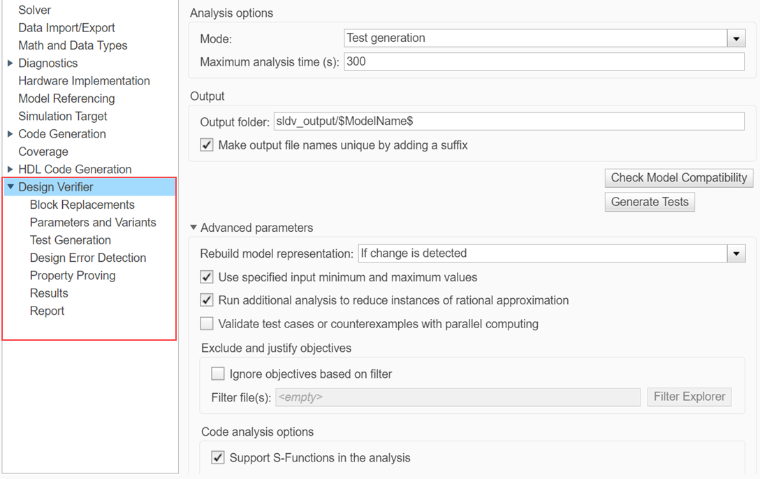
Design Verifier Pane
In Design Verifier pane, you specify analysis options and configure Simulink Design Verifier output.
| Parameter | Description |
|---|---|
| Mode | Specify the analysis mode for Simulink Design Verifier. |
| Maximum analysis time | Specify the maximum time (in seconds) that Simulink Design Verifier spends analyzing a model. |
| Output folder | Specify a path name to which Simulink Design Verifier writes its output. |
| Make output file names unique by adding a suffix | Specify whether Simulink Design Verifier makes its output file names unique by appending a numeric suffix. |
These configuration parameters are in the Advanced parameters section.
| Parameter | Description |
|---|---|
| Rebuild model representation | Specify whether to rebuild model representation for Simulink Design Verifier analysis. |
| Use specified input minimum and maximum values | Specify whether to generate test cases that consider specified minimum and maximum values as constraints for all input signals in your model. |
| Run additional analysis to reduce instances of rational approximation | Specify whether Simulink Design Verifier attempts to reduce the use of rational approximation during analysis. |
| Validate test cases or counterexamples with parallel computing | Validate test cases or counterexamples with parallel computing. |
| Ignore objectives based on filter | Specify to analyze the model, ignoring the objectives in Filter file(s). |
| Support S-Functions in the analysis | Specify whether to support S-Functions in the analysis. |
| Ignore the volatile qualifier | Specify whether to ignore the volatile qualifier when analyzing the model. |
| Additional options for code analysis | Specify additional options for analyzing S-functions that have been compiled to be compatible with Simulink Design Verifier. |
For more information on the parameters within Design Verifier pane in the Configuration Parameters dialog box, see: