Dead Logic Detection
Dead logic represents elements of your model which cannot be active during simulation. Dead logic detection identifies decision coverage and condition coverage outcomes that cannot occur. In some cases dead logic arises due to errors within your designs. Before you simulate a model, use dead logic detection to analyze the model for dead logic. In Simulink® Design Verifier™, design error detection for dead logic consists of two analysis options:
Dead logic (partial): If you select this option, Simulink Design Verifier analyzes your model without making any approximations, such as rational approximation for floating points, or while loop approximation. For more information, see Approximations During Model Analysis. With this option, Simulink Design Verifier does not report active logic or undecided objectives and it may not identify some dead logic in your model.
This option is available in:
The Model Advisor. See Check For Design Errors using the Model Advisor.
The Configuration Parameters dialog box, on the Design Verifier > Design Error Detection pane.
Run exhaustive analysis: With this option, Simulink Design Verifier reports active logic in addition to dead logic as well as undecided objectives. This option may in some cases identify or find additional dead logic. The analysis may use approximations and are reported accordingly.
This option is available in Configuration Parameters dialog box, on the Design Verifier > Design Error Detection pane.
Run a Partial Check for Dead Logic
If you are not using the Model Advisor, to detect dead logic:
On the Design Verifier tab, in the Mode section, select Design Error Detection.
Click Error Detection Settings.
In the Configuration Parameters dialog box, on the Design Verifier > Design Error Detection pane:
Enable the Dead logic (partial) option.
Clear the Run exhaustive analysis option, if it is selected.
Set Coverage objectives to be analyzed to
MCDC. The available options from the drop-down menu areDecision,Condition Decision, andMCDC.
To apply these settings, click OK and close the Configuration Parameters window.
Click Detect Design Errors.
Run an Exhaustive Analysis for Dead Logic
On the Design Verifier tab, in the Mode section, select Design Error Detection.
Click Error Detection Settings.
In the Configuration Parameters dialog box, on the Design Verifier > Design Error Detection pane:
Enable the Dead logic (partial) option.
Select the Run exhaustive analysis option.
Set Coverage objectives to be analyzed to
MCDC. The available options from the drop-down menu areDecision,Condition Decision, andMCDC.
To apply these settings, click OK and close the Configuration Parameters dialog box.
Click Detect Design Errors.
Run a Dead Logic Analysis and Review Results
This example shows how to detect dead logic in the
sldvSlicerdemo_dead_logic example model. Dead logic detection
finds the unreachable objectives in the model that cause the model element to remain
inactive.
Open the
sldvSlicerdemo_dead_logicmodel.openExample('slcheck/AnalyzeTheDeadLogicExample',... 'supportingFile','sldvSlicerdemo_dead_logic');
On the Design Verifier tab, in the Mode section, select Design Error Detection.
Click Error Detection Settings.
In the Configuration Parameters dialog box, on the Design Verifier > Design Error Detection pane:
Enable the Dead logic (partial) option.
Clear the Run exhaustive analysis option, if it is selected.
Set Coverage objectives to be analyzed to
MCDC. The available options from the drop-down menu areDecision,Condition Decision, andMCDC.
Click Detect Design Errors.
The software analyzes the model for dead logic and displays the results in the Results Summary window. The result indicates that
8of the32objectives were found to be dead logic.Click Highlight analysis results on model. The dead logic model elements are highlighted in red.
Open the
Controllersubsystem, and click the OR block highlighted in red. The Result Inspector displays the summary of the dead logic.The
setinput is equal to1, so theinput port 1of the OR block can only be true. The status implies that theinput port 1false condition is a dead logic. Similarly, theinput port 2isunreachable, as the objective never executes and is dead logic.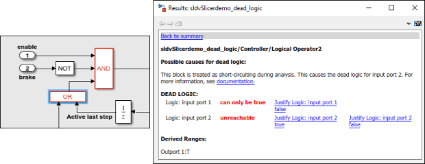
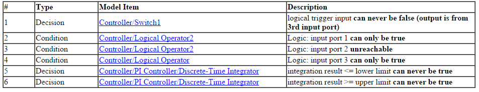
To view the detailed analysis report, in the Results Summary window, click HTML.
The report displays the summary of all the results that are dead logic in the model.
Dead Logic
The software stores the detailed analysis results in the
DeadLogic fieldin the View and Understand Analysis Results from Data Files. You can use the data file for further analysis of the results.
Suggestion:
You can use Model Slicer to find the parameters which could have an impact on a particular block by following these steps:
a. Create an object of SLSlicerAPI.ParameterDependence using Model
Slicer.
slicerObj = slslicer('sldvSlicerdemo_dead_logic');
pd = slicerObj.parameterDependence;
b. Find the parameters affecting the Discrete-Time Integrator block.
param = parametersAffectingBlock(pd, 'sldvSlicerdemo_dead_logic/Controller/PI Controller/Discrete-Time Integrator');
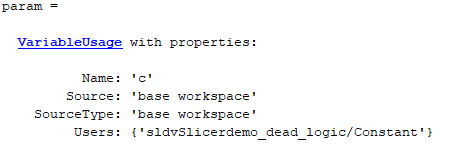
The image above displays the parameters returned by the function
parametersAffectingBlock which have an impact on the
Discrete-Time Integrator block. The parameters returned by the
function can be considered for tuning.
c. Perform clean-up to exit compile state of the model.
slicerObj.terminate;