Achieve Coverage in Models with Variable-Size Inputs
This example shows you how to achieve model coverage in models with variable-size input signals by using Simulink® Design Verifier™.
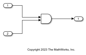
Open the Model
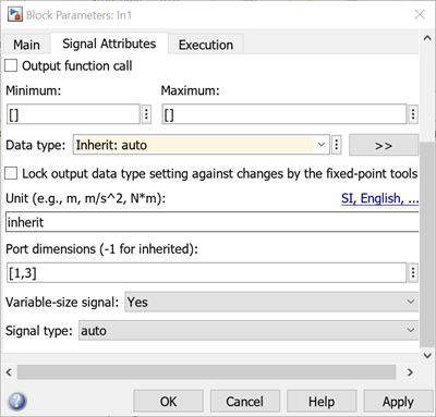
The model in this example has two input ports that pass variable-size signals. Input port 1 (in1) of the model is of variable size signal with maximum dimension [3,3].
open_system('sldvVariableSizeAtInport');
Create and Detach Harness Model
1. Open Simulink Test in the Apps pane.
2. Click Add Test Harness in the Create Test Harness section.
3. Click OK in the Create Test Harness dialog box.
4. Click Detach And Export in the Harness tab.
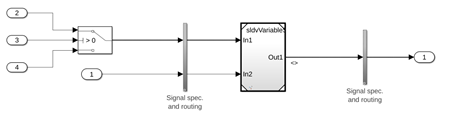
Drive Variable-size Input Port with Fixed Dimension Signals
Simulink Design Verifier™ supports models with fixed-size signals at the input ports. Enhance the harness model such that it has fixed-size input ports but produces variable-size signals at the design interface.
1. Add a Switch block to the harness model and in the Block Parameters dialog box on the Signal Attributes tab, select Allow different data input sizes checkbox.
2. Set the dimensions of the two data ports of the Switch block to [3,3] and [2,2] to ensure that you have a variable-dimension signal in1 of the design model.
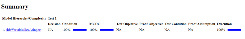
Generate Tests to Achieve Coverage
1. Open Design Verifier in the Apps pane of the updated harness.
2. Click Generate Tests in the Analyze section.
3. Click Simulate tests and generate the model coverage report in the Results summary window.