Logical Operator Cascade Patterns
This example shows how Simulink® Coverage™ analyzes logical operator blocks when they are downstream of other logical operator blocks.
Example Model Overview
The example model contains various patterns of cascaded Logical Operator blocks. This example illustrates the criteria by which Simulink Coverage identifies logical operator block cascades for the purpose of model coverage analysis for the Modified Condition Decision Coverage (MCDC) metric.
The example model contains patterns of Logical Operator block cascades.
open_system('slcoverage_mcdc_logic_cascade');When you analyze a model for MCDC, Simulink Coverage searches for cascades of logical operator blocks. A logic cascade occurs when there are logical operator blocks downstream of other logical operator blocks. When Simulink Coverage identifies a logic cascade, it analyzes the overall expression represented by the combination of blocks, instead of analyzing each block individually. If a logical operator block is not part of a logic cascade, then you only receive MCDC results for the individual block.
Logical Operator blocks only receive MCDC as part of a logic cascade when these conditions are true:
Block input and output signals are all scalar.
The block operation is not XOR/NXOR
The block has more than one input signal (unless its operation is NOT)
The input signal does not branch to another non-virtual block
Simulate the model by clicking Run (Coverage). When the simulation is finished, the Coverage Details pane opens.
sim('slcoverage_mcdc_logic_cascade');View the First Cascade
Click the And block And_Block.

The coverage report for And_Block displays three conditions and each condition has two possible outcomes. Only one outcome is satisfied. However, And_Block does not display an MCDC table. This happens because Simulink Coverage identified And_Block as part of a logic cascade. Instead, the MCDC line in the report links to the block that represents the root of the logic cascade, Not_Block. Click the link see Not_Block.
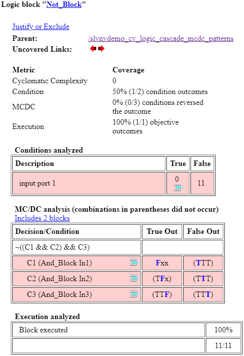
The coverage report for Not_Block displays one condition with two possible outcomes. In the coverage details for this block, however, there is an MCDC analysis table. This MCDC table displays the coverage results for the combined output of the logic cascade of And_Block and Not_Block. And_Block represents the logical operation C1 && C2 && C3 where each input is a Boolean value. Then, Not_Block negates this, so Simulink Coverage analyzes the overall expression ~(C1 && C2 && C3) in the MCDC analysis table. Because only one condition outcome occurred during the simulation, there are no satisfied MCDC outcomes for this cascade.
View the Second Cascade
Click Nor_Block.
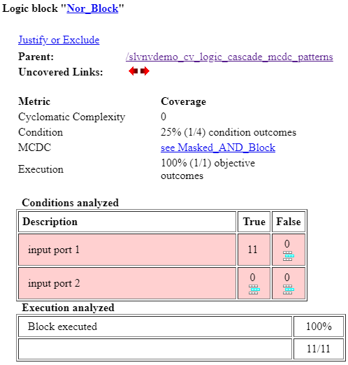
Similar to And_Block, Nor_Block displays the condition table with one satisfied outcome, but no MCDC analysis table. The MCDC line of the report links to Masked_AND_Block, which is inside the Masked Subsystem. In the model, click Masked Subsystem.
The second cascade is separate from the first cascade because the output signal of the first cascade, which is also the input signal to the second cascade, branches. If the signal branches only to a virtual block, then the MCDC cascade continues uninterrupted. If the signal branches to a non-virtual block, then Simulink Coverage treats them as two separate logical cascades.
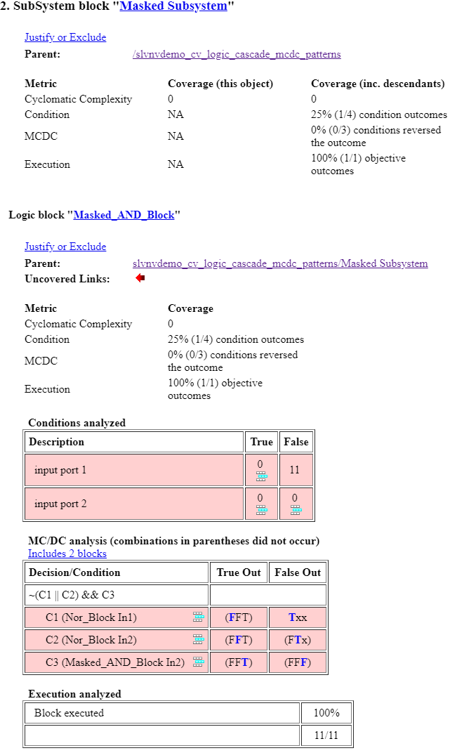
Masked Subsystem is a subsystem that contains Masked_AND_Block. The first input to the masked subsystem block is a virtual connection to the output of Nor_Block. You can see from the MCDC table that this does not prevent analysis of the cascaded logic. The Nor_Block represents the logical expression C1 || C2, and the Masked_AND_Block combines the output of that expression with a third Boolean value, C3, giving a cascaded logical expression of ~(C1 || C2) && C3. The MCDC table also displays the expression that represents the cascaded logic.
Unsupported Logical Operations
Click Or_Block.
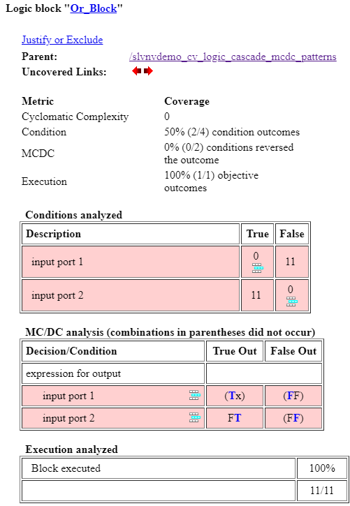
The coverage report displays the condition table and the MCDC table for this block. Now click XOR_Block.
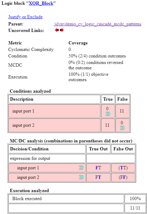
The coverage report also displays both analysis tables here. This happens because the XOR and NXOR operations are not supported for cascaded MCDC analysis. As a result, Simulink Coverage analyzes the MCDC for these blocks individually.
Click Vector_AND_Block to see that the report for this block also contains an MCDC analysis table. Vector inputs to logical operator blocks are not supported for cascaded MCDC analysis.