Identify and Resolve Missing Coverage Caused by Dead Logic
This example shows how to use Simulink® Design Verifier™ to identify and resolve missing coverage associated with dead logic in the Simulink Coverage™ report.
Dead Logic
Dead logic is unreachable or unused code or blocks in your model. When there is no combination of model inputs that can result in a condition being true or false, then the true or false case of that condition is dead logic. When you test your model, dead logic causes unsatisfied coverage outcomes in the coverage results. In most cases, dead logic is a design error. As a best practice, remove dead logic, if possible.
Although you can justify dead logic in your model, some domains and regulatory authorities have different guidelines about dead logic. For example, projects that require DO-178 qualification or ISO26262 certification have stricter requirements. Examples of acceptable dead logic may include:
In Stateflow® charts that use C as the action language, the
tickevent reports condition coverage and modified condition decision coverage (MCDC). Thetickevent cannot be false, so it is dead logic. You can justify the unsatisfiable coverage outcomes or use MATLAB® as the action language.If your model uses Simulink variant blocks as reusable components, such as in a model reference, and you do not use all of the variant configurations, the unused variant configurations are dead logic. You can justify unsatisfiable coverage outcomes or change the reusable component. For more information about variant blocks, see Model Coverage for Variant Blocks.
Open Model
Open the model.
modelName = "slcov_powerwindow_deadlogic";
open_system(modelName);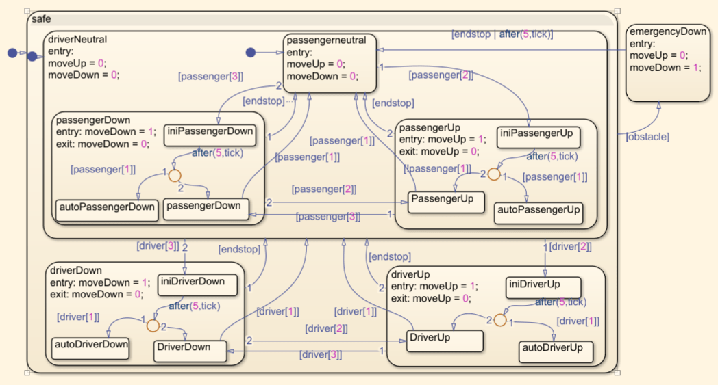
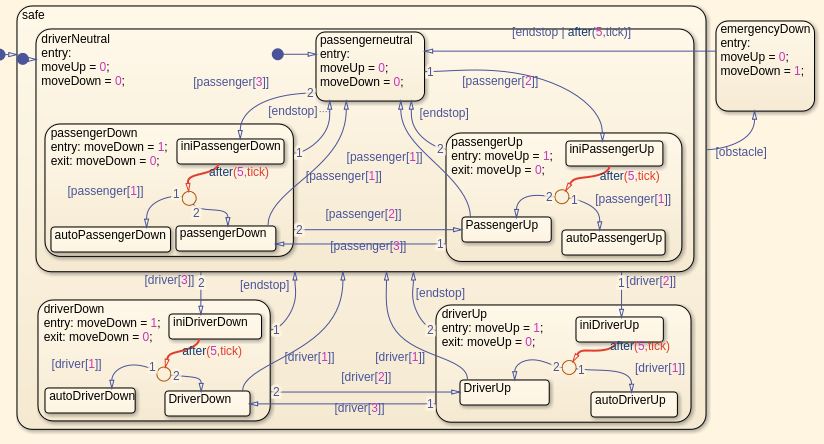
The slcov_powerwindow_deadlogic model models a power window controller by using a Stateflow chart. The power window controller responds to the driver and passenger commands to move the window up or down. If the power window detects an obstacle, the controller gives the down command for one second. If the driver presses the down button for less than one second, the controller gives the down command until the end has been reached or the driver presses the up button.
Run Coverage Analysis
In the Simulink Toolstrip, on the Coverage tab, click Analyze Coverage. Alternatively, run the coverage analysis programmatically by entering:
sim(modelName);
cvmodelview(covdata);
Run Dead Logic Detection
In the Coverage Details pane, scroll up the Missing Model Coverage Analysis section. This section appears when the model contains unsatisfied coverage outcomes.
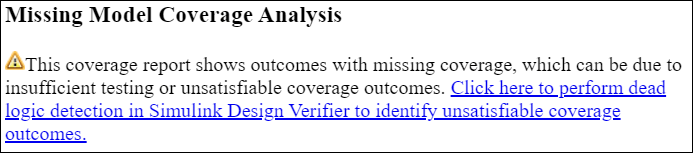
Click the link to open the Perform Dead Logic Detection dialog box.
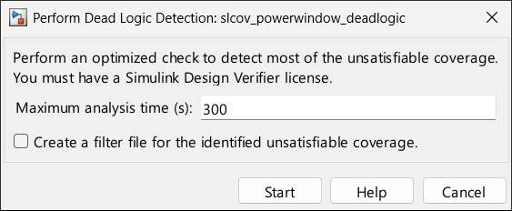
Use this dialog box to set the maximum analysis time and to specify whether to create a coverage filter and add justification rules for the dead logic that Simulink Design Verifier identifies. As a best practice, review the dead logic detection analysis results and address dead logic that is due to design errors, and manually justify dead logic that is acceptable. If your model requires DO-178 or ISO26262 certification, the Create a filter file for the identified unsatisfiable coverage option is not recommended.
Click Start.
Analyze Dead Logic Detection Results
After the analysis completes, double-click the Stateflow chart control. Simulink Design Verifier highlights dead logic in red. In this example, the analysis identifies five conditions as dead logic.
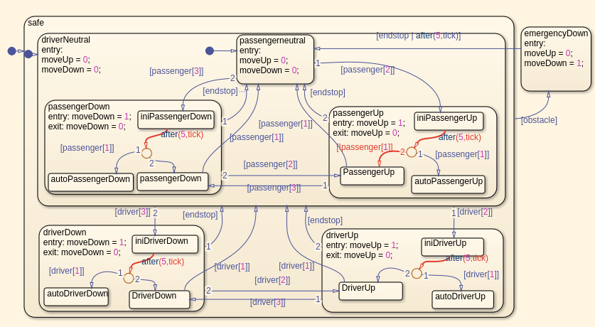
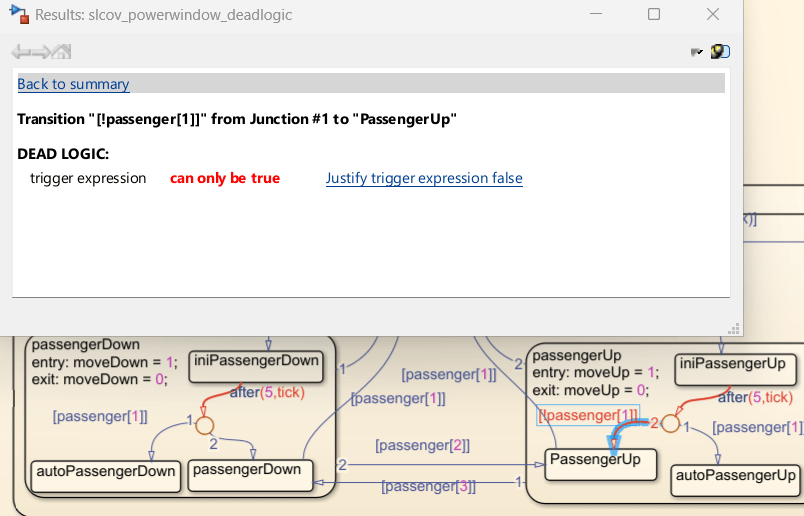
Click the [!passenger[1]] transition in the passengerUp subchart. The Results window displays information about the dead logic.
Resolve Missing Coverage Associated with Dead Logic
In the passengerUp substate, transitioning out of the iniPassengerUp state can take two paths. When passenger[1] is true, the chart transitions to the autoPassengerUp state, and when passenger[1] is false, it takes the other transition. In this chart, the other transition contains the decision [!passenger[1]]. Because this chart uses C as the action language, ! is the NOT operator, which makes !passenger[1] the opposite of passenger[1]. This means that the [!passenger[1]] transition can never be false because in every case where it is false, the chart takes the [passenger[1]] transition instead. When this happens, the logic is overspecified.
There are two ways to address the missing coverage:
Justify the false outcome of the
[!passenger[1]]transition decision.Edit the model to remove the dead logic.
In this example, the overspecified transition adds nothing to the model. In the model, click in the [!passenger[1]] transition inside the passengerUp substate, and delete the transition condition, then click anywhere on the canvas to exit editing the state.
Close the Simulink Design Verifier results by clicking Close, then click Analyze Coverage again. To analyze dead logic again, in the Coverage Details, scroll to Missing Model Coverage Analysis, click the link, then click Start. Simulink Design Verifier does not identify dead logic on the second transition from iniPassengerUp.
Click the transition from the iniPassengerUp substate that contains the condition after(5,tick).
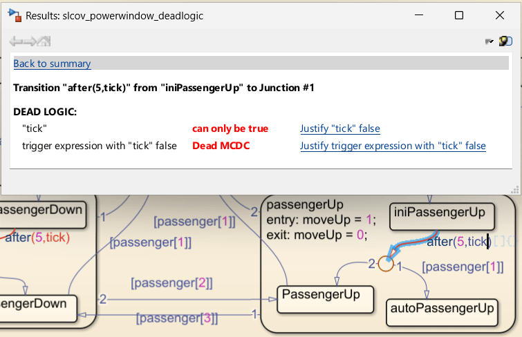
The Results window displays two coverage outcomes because Simulink Design Verifier analyzes dead logic for decision, condition, and MCDC outcomes, even when you do not enable those metrics. Justify the missing condition outcome by clicking Justify "tick" false in the Results window, and justify the missing MCDC outcome by clicking Justify trigger expression with "tick" false. When you click the justify links in the Simulink Design Verifier results, the Filter Explorer window opens. In the Filter Explorer, you can name the filter, give it a description, and add rationales to the filter rules. For this example, set the Filter Name to filter_tick, set the Description to Filter dead logic associated with tick, and set the rationales to tick dead logic, then click Apply. In the Save Filter dialog box, set the file name to filter_tick and click Save.
When you apply the filter, the Coverage Details pane opens and highlights coverage results on the model. To return to the Simulink Design Verifier results, in the Simulink Design Verifier Results Summary window, click Highlight analysis results on model. There are four tick events in the chart, and each tick event contains one unsatisfiable decision outcome and one unsatisfiable MCDC outcome. Review and decide whether to fix or create filter rules for each piece of dead logic.
See Also
slcoverage.Filter | slcoverage.FilterRule