Chirp Input Signals
R2026bA swept-frequency cosine input signal, or chirp signal, excites your system at a range of frequencies, such that the input frequency changes instantaneously.
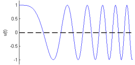
You can use a chirp input signal for frequency-response estimation at the command line or in Model Linearizer. The estimation algorithm injects the chirp signal at the input point you specify for estimation, and measures the response at the output point. Chirp signals are useful when your system is nearly linear in the simulation range. They are also useful when you want to obtain a response quickly for a lot of frequency points. The frequency-response model that results when you use a chirp input contains only frequencies that fall within the range of the chirp.
Create Chirp Signals Using Model Linearizer
In the Model Linearizer, to use a chirp input signal for estimation, in the Estimation tab, select Input Signal > Chirp. You can specify the frequency range and other properties of the chirp in one of two ways:
Enter the values manually in the Create chirp input dialog box.
Initialize the frequencies based on the dynamics of a linear model, such as a linearization of your system.
To create a chirp signal based on a linear model:
Obtain a linearized model,
linsys1.For example, see Linearize Simulink Model at Model Operating Point, which shows how to linearize a model.
In the Model Linearizer, in the Estimation tab, select Input Signal > Chirp.
The Create chirp input dialog box opens.
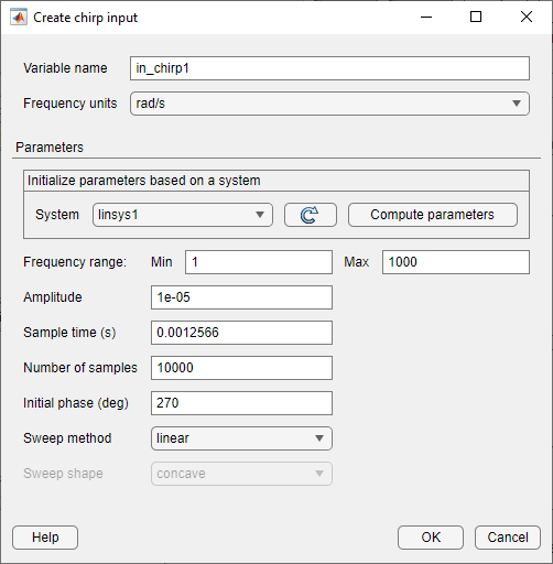
In the System list, select
linsys1. Click Compute parameters.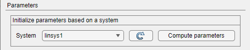
The software automatically selects frequency points based on the dynamics of
linsys1. The software also automatically determines other parameters of the chirp signal, including:Frequency range — Range of frequencies for the chirp, which the software chooses based on the frequencies at which the linear system has interesting dynamics.
Amplitude — Amplitude of applied perturbation.
Sample time — Sample time of signal. To avoid aliasing, the software chooses the sample time such that the Nyquist frequency of the signal is five times the upper end of the frequency range, .
Number of samples
Initial phase
Sweep method
Sweep shape
Click OK to create the chirp input signal. A new input signal
in_chirp1appears in the Linear Analysis Workspace.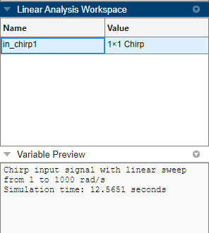
You can now select this signal in the Input Signal drop-down list for estimation.
The mapping between the parameters of the Create chirp input dialog box in the
Model Linearizer and the properties of
frest.Chirp is as follows:
| Create chirp input dialog box | frest.Chirp property |
|---|---|
| Frequency range > From | First element associated with the
'FreqRange' option |
| Frequency range > To | Second element associated with the
'FreqRange' option |
| Amplitude | 'Amplitude' |
| Sample time (sec) | 'Ts' |
| Number of samples | 'NumSamples' |
| Initial phase (deg) | 'InitialPhase' |
| Sweep method | 'SweepMethod' |
| Sweep shape | 'Shape' |
Create Chirp Signals Using MATLAB Code
To create a chirp signal for estimation at the command line with
frestimate, use frest.Chirp. See that page
for examples and more information about chirp signal properties.

