Zero-Crossing Detection with Fixed-Step Simulation
Models with both continuous states and discontinuous signals may require a small fixed-step size to obtain accurate simulation results near discontinuities. With fixed-step zero crossing enabled, Simulink® can automatically detect and locate discontinuities and correct the continuous states in the model. This functionality allows you to use a larger step size and enables faster simulation times without affecting simulation accuracy.
You may find fixed-step zero-crossing detection useful if your model contains:
Continuous states
Blocks with zero-crossings driven by signals with continuous sample time
Frequent switching or other events that limit solver step-size
Effects of Zero-Crossing Detection in Fixed-Step
Consider a self-resetting integrator that can be used to generate a sawtooth wave where the state is reset to 1/3 each time it reaches a value of 1. Simulating in variable-step with zero-crossing detection shows the expected results, or baseline, for this model.

model = 'mSelfResetIntegrator';
open_system(model);

set_param(model, 'Solver', 'ode23');
simoutVS = sim(model);
figure();
plot(simoutVS.tout, simoutVS.xout);
legend('Variable-Step (baseline)',...
    'Location', 'southeast');
The sawtooth wave generated using variable-step simulation is used as a baseline.

Simulate in Fixed-Step Without Zero-Crossing Detection
You can use a fixed-step solver like ode3 to simulate this model
with default fixed-step size equal to 0.2. However, the simulation results are not very
accurate for this step size. The fixed-step size must be decreased to about 0.001 for
the simulation results that align with the expected result.
set_param(model, 'Solver', 'ode3', ...
    'FixedStep', '0.2');
simoutFS = sim(model);

plot(simoutVS.tout, simoutVS.xout, ...
    simoutFS.tout, simoutFS.xout, '-x');
title('Fixed-step size = 0.2');
legend('Variable-Step (baseline)', 'Fixed-step (Zero-Crossing Disabled)',...
    'Location', 'southeast');

set_param(model, 'FixedStep', '.001');
simoutFS2 = sim(model);

plot(simoutVS.tout, simoutVS.xout, ...
    simoutFS2.tout, simoutFS2.xout, '-x');
title('Fixed-step size = 0.001');
legend('Variable-Step (baseline)', 'Fixed-step (Zero-Crossing Disabled)',...
    'Location', 'southeast');

Enable Fixed-Step Zero-Crossing Detection
Zero-crossing detection can be enabled for this model by selecting Enable zero-crossing detection for fixed-step simulation. You can also set the step size back to 0.2 and simulate. Note that despite this substantial increase in step size, each state value in this simulation coincides with the expected result. Thus, zero-crossing detection for fixed-step simulation results in faster simulation times for this model.
set_param(model, 'FixedStep', '0.2', ...
    'EnableFixedStepZeroCrossing', 'on');

simoutFSZC = sim(model);
plot(simoutVS.tout, simoutVS.xout, ...
    simoutFSZC.tout, simoutFSZC.xout, '-x');
title('Fixed-step size = 0.2');
legend('Variable-Step (baseline)', 'Fixed-step (Zero-Crossing Enabled)',...
    'Location', 'southeast');

Set Parameters for Zero-Crossing Detection
You use two main parameters to control zero crossing for fixed-step simulation. These parameters help ensure that the detection and location of zero-crossing events is fixed-cost. Go to the Solver Details > Zero-crossing options section of the configuration parameters to access the parameters.

Maximum Number of Bracketing Iterations
The Maximum number of bracketing iterations parameter limits the number of search iterations used by Simulink for locating a zero-crossing event once the event has been detected. In general, a higher number of bracketing iterations will provide a more accurate event location, but this option is computationally costly.
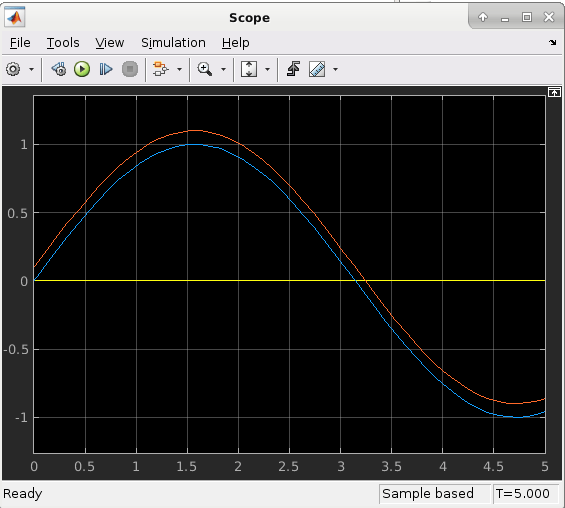
Consider this model with a sine wave driving a Hit Crossing block. Zero-crossings are detected when the Hit Crossing block detects that its input signal has crossed zero, which should occur at multiples of pi. The scope displays this result.

model = 'mFixedStepZcParameters';
open_system(model);
set_param(model, 'Solver', 'VariableStepAuto');
sim(model);

Too few bracketing iterations results in locating zero crossings with less accuracy. To see the number of bracketing iterations simulation results, enable fixed-step zero-crossing, change to a fixed-step solver, and set the Maximum number of zero-crossings per step parameter to 2. Use a fixed-step size of 0.5.

set_param(model, 'EnableFixedStepZeroCrossing', 'on',...
    'MaxZcBracketingIterations', '2',...
    'SolverName', 'ode3',...
    'FixedStep', '0.5');
Increasing the number of bracketing iterations to 4 results in more accurate location of the events in this model. The zero crossing is located closer to the expected value of pi.

set_param(model, 'MaxZcBracketingIterations', '4');
Maximum Number of Zero-Crossings per Step
Use Maximum number of
zero-crossings per step parameter to limit the maximum number of zero
crossings that Simulink will locate in one simulation time step. Once this maximum number is reached
in a step, any additional zero-crossings that occur within that step are ignored. To see how
this can affect simulation results, consider the following example. Set the Sine
Wave block to output two sine waves that are slightly offset by using scalar
expansion on the 'Bias' parameter of the sine wave block. Two zero
crossing events should be located near pi.
sineWaveBlock = [model '/Sine Wave'];
set_param(sineWaveBlock, 'Bias', '[0.0 0.1]');
set_param(model, 'Solver', 'ode45');
simoutVS = sim(model);
Setting the maximum number of zero-crossings to locate per step to 1 will restrict Simulink to only locating the first zero crossing that occurs within a single time step. In this example, Simulink only locates the first zero-crossing in the step at pi in the step from t = 3 to t = 3.5. As a result, the second state of the Integrator block is less accurate due to the missed zero crossing.
set_param(model, 'Solver', 'ode3',...
    'EnableFixedStepZeroCrossing', 'on',...
    'MaxZcPerStep', '1');
simoutFS_1ZC = sim(model);
f = figure();
tiledlayout(f,'flow','TileSpacing','compact','Padding','compact');
nexttile;
plot(simoutVS.tout, simoutVS.xout.signals(1).values(:, 1),...
    simoutFS_1ZC.tout,simoutFS_1ZC.xout.signals(1).values(:,1), '-x');
title('State 1')
nexttile;
plot(simoutVS.tout, simoutVS.xout.signals(1).values(:,2),...
    simoutFS_1ZC.tout,simoutFS_1ZC.xout.signals(1).values(:,2), '-x');
title('State 2')
legend('Variable-Step (Expected Result)', 'Fixed-Step with One Zc Per Step',...
    'Location', 'northwest');


Since you know to expect a maximum of two zero crossings to be located within the fixed-step size of 0.5, setting the Maximum number of zero-crossings per step parameter to 2 should yield more accurate simulation results. This plot shows that both continuous states of the Integrator block match the expected result.
set_param(model, 'MaxZcPerStep', '2')
simoutFS_2ZC = sim(model);
f = figure();
tiledlayout(f,'flow','TileSpacing','compact','Padding','compact');
nexttile;
plot(simoutVS.tout, simoutVS.xout.signals(1).values(:, 1),...
    simoutFS_2ZC.tout,simoutFS_2ZC.xout.signals(1).values(:,1), '-x');
title('State 1')
nexttile;
plot(simoutVS.tout, simoutVS.xout.signals(1).values(:,2),...
    simoutFS_2ZC.tout,simoutFS_2ZC.xout.signals(1).values(:,2), '-x');
title('State 2')
legend('Variable-Step (Expected Result)', 'Fixed-Step with Two Zc Per Step',...
    'Location', 'northwest');


See Also
Maximum number of bracketing iterations | Enable zero-crossing detection for fixed-step simulation | Maximum number of zero-crossings per step | Zero-Crossing Detection | Zero-Crossing Algorithms