Print Model Diagrams
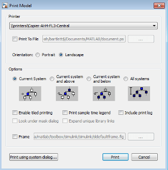
To print a model diagram, in the Simulink® Editor, on the Simulation tab, click Print.
Print Models Using Default Settings
The default print settings produce good quality printed output for quickly capturing a model in printed form.
Open your model.
In the Simulink Editor, on the Simulation tab, click Print.
In the Print Model dialog box, use the default settings. Click Print.

The model as it appears in the Simulink Editor prints on a single page using portrait orientation and without a print frame.
Specify Paper Size and Orientation
Use the Print Model dialog box to specify the page orientation (portrait or landscape) for the current printing session.
To specify paper size and orientation without printing, use the Page Setup dialog box. To open the dialog box, on the Simulation tab, select Print > Page Setup. Only the paper size and orientation are used.
Specify Background Color
By default, the canvas (background) of the printed model is white. To match the color of the model, set the Simulink Preferences > General > Print.
Specify Print Frames
Print frames are borders of a printed page that contain information about a block diagram, such as the model name or the date of printing.
To print using a print frame, specify an existing print frame. If you want to build a print frame, see Create Print Frames for Printed Pages.
Note
If you enable the print frame option, then Simulink does not use tiled printing.
In the Simulink Editor or Stateflow® Editor, on the Simulation tab, click Print.
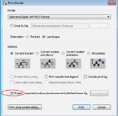
In the Print Model dialog box, select the Frame check box.

Supply the file name for the print frame you want to use. Either type the path and file name directly in the edit box, or click the ... button and select a print frame file you saved using the PrintFrame Editor. The default print frame file name,
sldefaultframe.fig, appears in the file name edit box until you specify a different file name.Specify other printing options in the Print Model dialog box.
Note
The paper orientation you specify with the PrintFrame Editor does not control the paper orientation used for printing. For example, assume you specify a landscape-oriented print frame in the PrintFrame Editor. If you want the printed page to have a landscape orientation, you must specify that using the Print Model dialog box.
Click OK.
The block diagram prints with the print frame that you specify.
Select the Systems to Print
To print the system in the currently open Simulink Editor tab, on the Simulation tab, click Print.
For models with subsystems, use the Simulink Editor and the Print Model dialog box to specify the subsystems to print.
Note
To print a model reference hierarchy, you must print each referenced model separately. You cannot print the contents of protected models.
By default, Simulink does not print masked subsystems or subsystems linked to libraries.
To print the contents of masked subsystems, in the Print Model dialog box, click Look under mask dialog.
To print the contents of library links, in the Print Model dialog box, click Expand unique library links. Simulink prints one copy, regardless of how many copies of the block the model contains.
If a subsystem is a masked subsystem linked to a library, Simulink uses the Look under mask dialog setting and ignores the Expand unique library links setting.
To print all of the subsystems in a model:
Display the top-level of a model in the currently open Simulink Editor tab.
In the Simulink Editor, on the Simulation tab, click Print.
In the Print Model dialog box, select All systems.
Click Print.
To print a subset of the subsystems in a model:
In the current tab of the Simulink Editor, display the subsystem level that you want to use as the starting point for printing the subsystem hierarchy.
In the Print Model dialog box, select one of the following:
Current system and below
Current system and above
Click Print.
Print Large Diagrams over Multiple Pages
By default, each block diagram is scaled during the printing process so that it fits on a single page. In the case of a large diagram, this automatic scaling can make the printed image difficult to read.
Tiled printing enables you to print even the largest block diagrams without sacrificing clarity and detail. Tiled printing allows you to distribute a block diagram over multiple pages. For example, you can use tiling to divide a model as shown in the figure, with each white box and each gray box representing a separate printed page.

You can control the number of pages over which Simulink prints the block diagram.
You can also set different tiled-print settings for each of the systems in your model.
Note
If you enable the print frame option, then Simulink does not use tiled printing.
To print multiple pages for large model:
In the Simulink Editor, open the model in the current tab.
On the Simulation tab, click Print.
In the Print Model dialog box, select Enable tiled printing.
Note
The default Enable tiled printing setting in the Print Model dialog box is the same as the Print > Enable Tiled Printing setting. If you change the Print Model dialog box Enable tiled printing setting, the Print Model dialog box setting takes precedence.
Confirm that tiling divides the model into separate pages the way you want it to appear in the printed pages. In the Simulink Editor, on the Simulation tab, select Print > Show Page Boundaries. The gray and white squares indicate the page boundaries.
Optionally, from the MATLAB® Command Window, specify the model scaling, tile margins, or both. See Set Tiled Page Margins.
Optionally, specify a subset of pages to print. In the Print Model dialog box, specify the Page Range.
Click Print.
Add Log of Printed Models
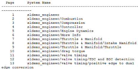
A print log lists the blocks and systems you have printed. To print the print log when you print a model:
In the Simulink Editor, open the model whose print job you want to log.
On the Simulation tab, click Print.
In the Print Model dialog box, select Include print log.
Click Print.
The print log appears on the last page.
For example, here is the print log for the sldemo_enginewc
model, with All systems enabled and Enable tiled
printing cleared.

Add Sample Time Legend
You can print a legend that contains sample time information for your entire system, including any subsystems. The legend appears on a separate page from the model. To print a sample time legend:
In the Simulink Editor, on the Modeling tab, click Update Model.
On the Simulation tab, click Print.
In the Print Model dialog box, select Print sample time legend.
Click Print.
A sample time legend appears on the last page. For example, here is the sample time
legend for the sldemo_enginewc model, with All systems
enabled.

For more information on sample times, see View Sample Time Information.
Configure Print Job
To open the print dialog box for your operating system, in the Print Model dialog box, click Print using system dialog. The operating system print dialog box provides additional printing options for models, such as page range, copies, double-sided printing, printing in color (if your print driver supports color printing), and nonstandard paper sizes.
Print Models to PDFs
You can print a model to a .pdf file. Simulink creates one file for all of the systems in the model.
In the Simulink Editor, on the Simulation tab, click Print.
Select Print to File.
Specify a location and file name to save the new
.pdffile. Include the extension.pdfin the file name.Click Print.
Copy Diagrams as Images
On Microsoft® Windows® platforms, you can copy the current view of your model in either a bitmap or metafile format. You can then paste the clipboard image to a third-party application, such as word processing software.
On Macintosh platforms, when you copy a model view to the clipboard, Simulink saves the model in a scalable format in addition to a bitmap format. When you paste from the clipboard to a third-party application, the application selects the format that best meets its requirements.
To copy a Simulink model to the operating system clipboard, in the Simulink Editor, on the Format tab, select Screenshot, then select the desired format.
Navigate out of Simulink and into a third-party application with image capabilities. Paste the model from the clipboard to the third-party application. Export the model image using the correct procedure for the application.
Note
The quality of the exported image will depend on the third-party application. Results may vary based on individual cases.
By default, the canvas (background) of the copied model matches the color of the model. To use a white or transparent canvas for copied model files, set the Simulink Preferences > General > Clipboard preference. For more information, see Simulink Preferences.