Establish Message Send and Receive Interfaces Between Software Components
This example shows how to model message-based communication between software components that run in different applications. The example also shows how to prepare model components for C++ code generation.
In this example, the message-based communication is constructed between two components. Send component sends data and receive component consumes data. In this scenario, after send component sends messages, they are stored in a queue. Receive component pulls a message based on the logic it represents.
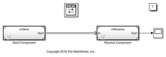
Two Model blocks, labeled Send Component and Receive Component, represent the components connected by a message line. Message-based communication is achieved using a Send block and a Receive block that are connected to the root-level Outport and Inport blocks.
For more information about generating C or C++ code for the model, see Generate C++ Messages to Communicate Data Between Simulink Components (Embedded Coder) and Generate C Messages to Communicate Data Between Simulink Components (Embedded Coder).
You can also generate C++ code for each component, and the code contains necessary software interfaces that are sufficient for you to connect with an operating system or message middleware. For more information, see Generate C++ Messages to Communicate Data Between Simulink and an Operating System or Middleware (Embedded Coder).
Send Component
The algorithm in the Send Component can contain logic of any complexity. In the example, a simple Sine Wave block is used in a subsystem as the signal source. The Sample time parameter of the block is set to 0.1.
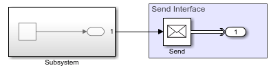
To prepare the Send Component for message-based communication, a Send block is connected to the root-level Outport block. The Send block converts data signals and send messages.
To prepare the Send Component for code generation, in the Model Configuration Parameters:
In the Solver pane, in the Solver selection section, the Type is set to
Fixed-step.The Fixed-step size is set to
0.1.In the Code Generation pane, the System target file is set to
ert.tlcand Language to C++.The model is saved as
mSend.
Receive Component
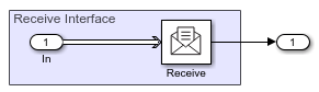
In the Receive Component, a Scope block is used to represent the algorithm that receives messages.
To prepare the Receive Component, the Inport block is connected to a Receive block. The Receive block receives messages and converts them to signal data. By default, the Sample time parameter of the Receive block is -1.
To prepare the Receive Component for code generation, in the Model Configuration Parameters:
In the Solver pane, in the Solver selection section, the Type is set to
Fixed-step.The Fixed-step size is set to
0.1.In the Code Generation pane, the System target file is set to
ert.tlcand Language to C++.The model is saved as
mReceive.
Visualize Message Transitions Between Components Using the Sequence Viewer Block
This is a composition model with Send and Receive components. The Model blocks, Send Component and Receive Component, refer to models mSend and mReceive, respectively.
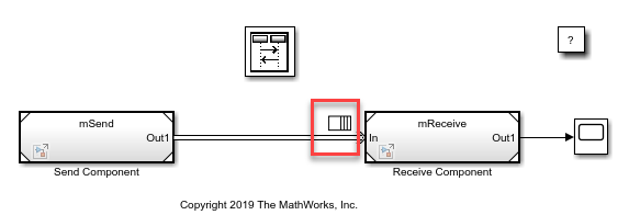
Simulate the model. Observe the queue inserted by default. An icon above the message line represents the default queue. The capacity of the default queue is 1 and the message overwriting policy is enabled. You can customize the queue by using a Queue block between components. For more information, see Use a Queue Block to Manage Messages.
Open the Sequence Viewer block. The block allows you to visualize message transition events and the data that the messages carry.
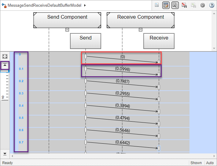
The Sequence Viewer block window shows the simulation time in the left vertical bar. Each time grid row contains events that occur at the same simulation time. Each message transition event is represented by an arrow that is labeled with the message data value. For more information about the Sequence Viewer block, see Use the Sequence Viewer to Visualize Messages, Events, and Entities.
In the Sequence Viewer block, scroll up or click Go to first event icon on the left. Observe that at time zero the Send block sends a message with data value 0 to the Receive block, and at time 0.1 the block sends another message with data value 0.0998. The block sends a message in every 0.1 simulation time.
See Also
Sine Wave | Send | Receive | Queue | Sequence Viewer
Topics
- Simulink Messages Overview
- Connect Message Receive Interface with Simulink Functions
- Generate C Messages to Communicate Data Between Simulink Components (Embedded Coder)
- Generate C++ Messages to Communicate Data Between Simulink Components (Embedded Coder)
- Generate C++ Messages to Communicate Data Between Simulink and an Operating System or Middleware (Embedded Coder)
- Model Message-Based Communication Integrated with POSIX Message Queues (Embedded Coder)
- Animate and Understand Sending and Receiving Messages