Create and Edit Signal Data
Use the Signal Editor to create and edit input signals that you can organize for multiple
simulations. You can then save the signal data to a MAT-file for simulation or to map to
root-level ports. By default, Signal Editor creates signal data in timeseries
format. You can access the Signal Editor in the following ways:
signalEditorfunction — Signal Editor starts from the command line.From the Root Inport Mapper — To create a MAT-file for your new signal data, select Signals > New MAT-File. To link in an existing signal data file from an existing scenario and edit the signals in that file, use the Signals > Edit MAT-File.
From the Signal Editor block
Signal Editor works only with MAT-files.
You can manipulate signals in these ways:
Create and edit multiple signals in multiple data sets. By default, Signal Editor creates
timeseriesformat data.Add the same signals to multiple scenarios simultaneously.
Edit signal properties for multiple signals simultaneously.
Use signal notations to create more complicated signals using MATLAB® expressions. You can use the Author Signal dialog box or manually enter simple MATLAB expressions in the tabular area.
Use existing scenarios to get existing data sets for which you can edit and create signals.
Create and edit multidimensional signals.
Edit signals imported as registered custom file types. For more information, see Import Custom File Type.
While editing signal data:
Use tabular editing or MATLAB to modify signal data.
Use mouse or multi-touch editing to graphically modify signal data.
Modify signal properties such as name, interpolation, and unit properties.
Drag and drop signals to change signal hierarchies for buses and data sets.
Use signal notations and variables to replace signal data.
Alternatively, you can:
Cut, copy, and paste data to and from Excel® spreadsheets.
Import data from external sources and edit them in Signal Editor. For more information, see Link in Signal Data from Signal Builder Block and Simulink Design Verifier Environment.
Use the Create Signal task to create signals in Live Editor.
To graphically create and edit signal data, see Create Freehand Signal Data Using Mouse or Multi-Touch Gestures.
Differences Between the Signal Editors
You can access the Signal Editor tool as a standalone tool, from the Root Inport Mapper, and from the Signal Editor block. The tool interface is generally the same regardless of how you access it.
Standalone Version
If you start the function with a model name, the signalEditor
function Signal Editor user interface shows the option Scenario from
Model in the Scenario section.
Root Import Mapper Version
The Scenario section Scenario drop-down list always has the option Scenario from Model.
Signal Editor Block Version
The Signal Editor block version of the tool has these differences:
In the Signal Editor block, when you click the Open Signal Editor button, the Signal Editor tool opens populated with the block active scenario and the active scenario from block icon
 .
.A new Active column in the signal hierarchy shows the active scenario for the block. To change the active scenario, click the associated button.
New input properties to support these corresponding block parameters.
Signal Editor Block Parameter Signal Editor Interface Input Property Output a bus signal
Output as bus object
Select bus object
Bus object
Enable zero-crossing detection
Enable zero-crossing detection
Form output after final data value by
Form output after final data value by
Sample time Sample time
Note
The Interpolate data and Unit parameters of the Signal Editor tool only reflect in the Signal Editor block when the block parameter Use properties from is set to
Signal data in MAT file.To change the active scenario in the Signal Editor tool, click the associated button in the signal hierarchy Active column and then click Save. Closing the tool updates the Signal Editor block.
Block parameters become read-only when you start the Signal Editor tool. To change control from the Signal Editor tool to the Signal Editor block, close the Signal Editor tool.
To see parameter changes for an active signal from the Signal Editor block in the associated Signal Editor tool, click the active signal in the signal hierarchy.
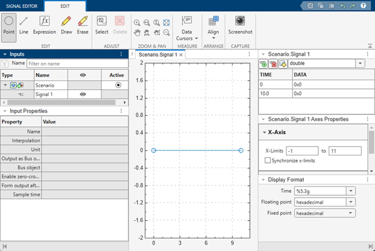
Table Editing Data Support
The Signal Editor user interface supports all signal data types that Simulink® supports and that are editable.
Add and Edit Multidimensional Signals
To add multidimensional signals, use either of these options:
In the Properties for Insertion dialog box, available by clicking Defaults in the Signals Editor tab, change the Dimensions property. For a multidimensional blank signal, enter a dimension greater than 1. Then, select Insert > Signal to insert a new basic signal. Observe that the new signal has multiple dimensions represented.

Enter multidimensional signal data in the Author and Insert dialog box Data parameter, such as
[(1:10)'
          (1:10)']
.
When you double-click ![]() for the signal, the tabular data area displays the signal
with columns for each dimension. You can edit the data individually in the tabular data area,
cut, copy, or replace data with Excel spreadsheets, or click the Replace button
for the signal, the tabular data area displays the signal
with columns for each dimension. You can edit the data individually in the tabular data area,
cut, copy, or replace data with Excel spreadsheets, or click the Replace button
![]() to replace the signal with a MATLAB expression. Use the Author and Replace Signal Data dialog box as though you are
inserting a new expression with the Author and Insert dialog box. For more information, see
Create Signals with MATLAB Expressions and Variables.
to replace the signal with a MATLAB expression. Use the Author and Replace Signal Data dialog box as though you are
inserting a new expression with the Author and Insert dialog box. For more information, see
Create Signals with MATLAB Expressions and Variables.
Tip
When replacing a signal, the signal dimension and complexity of the new signal must be the same as the signal being replaced.
For example, to create signal data with two columns and time from 1 to 10:
In Signal Editor, select Insert > Author Signal.
Enter signal data with two columns and time from 1 to 10:
Time —
[1:10]Data —
[(1:10)' (1:10)']
![Author and Insert dialog box with time = [1:10] and data = [(1:10)' (1:10)'](data_import_author_multi.png)
Click Insert Signal.
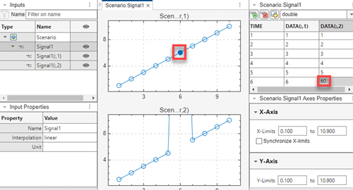
The hierarchy updates with the new signal data.
Expand the new signal and double-click
 for the signal. Observe the associated plots and the
tabular data for the signal.
for the signal. Observe the associated plots and the
tabular data for the signal.![Hierarchy and plot of time = [1:10] and data = [(1:10)' (1:10)']](data_import_author_multi_plot.png)
Tip
If the data does not plot as expected, click Fit to view in the Zoom & Pan section. For multidimensional signals, also make sure that you have the right plot selected for the column data you are editing.
You can edit the data directly in the table.
To replace data completely with a new expression by clicking Replace and entering a new time range and data in the Author and Replace Signal Data dialog box.
Tip
Selecting a point in the plot highlights the associated data in the table. Vice versa, selecting a data point in the table highlights the associated point in the plot.
Deleting a point in the plot deletes the associated data in the table. Vice versa, deleting a data point in the table deletes the associated point in the plot.
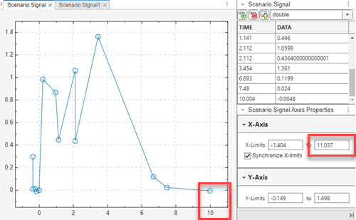
To synchronize all the signals in open plots by time (x-axis), select Synchronize X-limits in the Synchronize.SignalX Axes Properties pane. Use this setting to also synchronize zooming, panning, and fit-to-plot.
Change x- and y-axes Limits
Change plot x- and y-axes limits in the SignalX.Scenario Axes Properties panes. When you change the limit, the plot adjusts your view.
For example, look at this plot and SignalX.Scenario Axes Properties
pane. The rightmost limit of the x-axis is 11.037.
The data in this plot is the same, but the plot has a rightmost x-axis
limit of 9.

Change Signal Data Output Format Settings
By default, the Signal Editor tool displays signal data in its data pane as
double, with a format that displays integers as whole numbers
(auto).
Floating-point and fixed-point data types display with their least significant digits.
To change display time and signal data formats in the Signal Editor tool, use
the Display Format pane. You can change the display format for time and
data. The Signal Editor tool preserves the display format settings across
Signal Editor sessions. For example, to change the time and format display to
use a formatting operator, for Time and Floating
point in Display Format, select %5.3g.
You can change the formatting operator as necessary. The Signal Editor tool
remembers the last five unique formatting operators.
![Hierarchy and plot of time = [1:10] and data = [(1:10)' (1:10)'] and display format %5.3g](data_import_author_multi_plot_format1.png)
The effect of the associated display format fields depends on the data type. For example, if the data type is double, setting Fixed point has no effect.
![Hierarchy and plot of time = [1:10] and data = [(1:10)' (1:10)'] and display format %5.3g, data type double](data_import_author_multi_plot_format1_double.png)
However, if the data type of this data is changed to a fixed-point value, then the Fixed point takes effect.
![Hierarchy and plot of time = [1:10] and data = [(1:10)' (1:10)'] and display format %5.3g, data type fixed-point](data_import_author_multi_plot_format1_fixed.png)
For more information on display formats, see Format Output and Formatting Text.
Draw a Ramp Using Snap to Grid for Accuracy
This example describes how to create a ramp signal by selecting some points in the canvas.
In the Signal Editor tab, select Insert > Signal.
Expand the new signal and double-click
for the signal. Observe the associated plots and the
tabular data for the signal.In the Edit tab, to line up the signal data values along horizontal and vertical lines, select Align > Snap X to Grid and Align > Snap Y to Grid.
Move and zoom also honor snap to grid settings.
In the canvas, use Erase to erase the second point.
In the canvas, add three points:
Two points horizontal to each other
One point set to the right at an angle to the other signals
In the Signal Properties section, in Name, change the signal name to
Rampand press Enter.
Save and Send Changes to the Root Inport Mapper Tool
When you are done adding and modifying signals and scenarios, use the Save button to save the changes to a MAT-file. The Signal Editor can also send the data to the Root Inport Mapper Tool:
If the Root Inport Mapper tool has the scenario loaded, the Root Inport Mapper tool updates with the new data.
If the Root Inport Mapper tool has the scenarios mapped and your changes affect the mapping, the Root Inport Mapper tool unmaps the scenario.
See Also
Blocks
Tools
Functions
Topics
- Create Freehand Signal Data Using Mouse or Multi-Touch Gestures
- Map Root Inport Signal Data
- View and Inspect Signal Data
- Import Signal Data for Root Inport Mapping
- Exporting Signal Group Data
- Map Signal Data to Root Input Ports
- Root Inport Mapping Scenarios
- Create Signal Data for Root Inport Mapping
- Create Custom File Type for Import