Find Simulink Context Menu Options
This page shows a general approach for finding an option in a Simulink® context menu. The information pertains to the context menus of the model canvas and model elements such as blocks, signal lines, and annotations. Because these context menus changed significantly from R2025b to R2026a, the page also provides lookup tables for some context menus, for example, the Constant block context menu. The tables list the R2025b options in the context menus and their locations in the corresponding R2026a context menus.
General Approach to Finding Simulink Context Menu Option
To find a Simulink context menu option, first, determine whether the option is a clipboard or formatting option. For example, cut and paste are clipboard actions. Auto-arrange, block rotation, and color changes are formatting options.
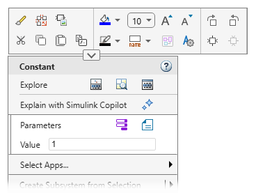
If the option is a clipboard or formatting option, look in the format bar. The format
bar is the part of the context menu that opens when you click the arrow
![]() at the top of the main body of the context menu.
at the top of the main body of the context menu.
If the option is not a clipboard or formatting option, determine whether the option belongs to an app. For example, if you want to add a Polyspace® annotation, the option belongs to the Polyspace Code Verifier app.
If the option belongs to an app, add the corresponding app section to the context menu. Pause your pointer on Select Apps, and then select the app. In the app section that appears, look for the option.

If the option is not a clipboard or formatting option and does not belong to an app, look for the option in the main body of the context menu.
Once you know in which part of the menu the option is located, scan the text of the menu items displayed in that part. If you do not see the option you are looking for, pause on the buttons to see their descriptions appear as tooltips.
If you still do not see the option, check the labels of any interactive menu elements such as radio buttons or check boxes. Then, check submenus menus by pausing on any arrows you see at the right edge of a menu item or button row.
Find R2025b Simulink Context Menu Options in R2026a
The tables show where you can find R2025b context menu options in R2026a.
Use the first table to find options that belong to apps. To access an option belonging to an app, you must add the corresponding app section to the context menu. The table lists some common R2025b options and their associated apps. If you are unsure whether a menu option you use is part of an app, or you know the option is part of an app but are unsure of which app, check this table.
The remaining tables show how you can access the R2025b options of these context menus in R2026a:
Constant block
Top model canvas
Signal line
Annotation
The tables list the options in the order in which they appear in the R2025b context menus. If an option is not available in the R2026a context menu, the table lists an alternative way to take the same action, if available.
App Options
| R2025b Context Menu Item | App |
|---|---|
| C/C++ Code | |
| Coverage | |
| Design Verifier | |
| Fixed-Point Tool | |
| HDL Code |
|
| Identify Modeling Clones | |
| Linear Analysis Points | |
| Metrics Dashboard | The options for this app are no longer available in the context menu. |
| Model Advisor | |
| Model Slicer | |
| Model Transformer | The options for this app are no longer available in the context menu. |
| Observers | |
| PLC Code | |
| Polyspace |
|
| Requirements or Requirements at This Level | |
| Test Harness |
|
Constant Block Context Menu
| R2025b Context Menu Option | Option in R2026a |
|---|---|
| Explore | Right-click the Constant block, and then click the Open in Model Explorer button
|
| Cut | Right-click the Constant block, and then click the Cut button |
| Copy | Right-click the Constant block, and then click the Copy button |
| Paste | Right-click the Constant block, and then click the Paste button |
| Comment Through | Right-click the Constant block, and then click the Comment Through button
|
| Comment Out | Right-click the Constant block, and then click the Comment Out button
|
| Uncomment | Right-click the Constant block, and then click the Uncomment button
|
| Find Referenced Variables | Navigate into the model or component whose referenced variables you want to find. Right-click the canvas, and then click the Referenced Variables button |
| Create Subsystem from Selection | Right-click the Constant block and select Create Subsystem from Selection. |
| Format > Arrange Automatically | Right-click the Constant block, click the arrow |
| Format > Show Block Name | Right-click the Constant block, and then click the arrow Name On, Name Off, or Auto Name. |
| Format > Foreground Color | Right-click the Constant block, and then click the arrow |
| Format > Background Color | Right-click the Constant block, and then click the arrow |
| Format > Rotate Clockwise | Right-click the Constant block, click the arrow |
| Format > Rotate Counterclockwise | Right-click the Constant block, click the arrow |
| Format > Flip Block | Right-click the Constant block, click the arrow |
| Format > Flip Block Name | Select the Constant block, and in the Simulink Toolstrip, on the Format tab, click Flip Name. |
| Format > Fit to Content | Select the Constant block, and in the Simulink Toolstrip, on the Format tab, click Fit to Content. |
| Format > Bring to Front | Select the Constant block. In the Simulink Toolstrip, on the Format tab, click the Bring to front button |
| Format > Send to Back | Select the Constant block. In the Simulink Toolstrip, on the Format tab, click the Send to back button |
| Mask > Create Mask | Right-click the Constant block and select Create Mask. |
| Mask > Add Icon Image | Right-click the Constant block and select Create Mask > Add Image. |
| Mask > Mask Parameters | Right-click the Constant block and select Edit Mask > Mask Parameters. |
| Mask > Look Under Mask | Right-click the Constant block and select Edit Mask > Look Inside Mask. |
| Requirements > Link to Selection in MATLAB Editor | Right-click the Constant block. To add the Requirements Manager app options to the menu,
point to Select Apps and click the Requirements Manager button
|
| Requirements > Link to Current Test Case | Right-click the Constant block. To add the Requirements Manager app options to the menu,
point to Select Apps and click the Requirements Manager button
|
| Requirements > Link to Selection in Safety Analysis Manager | Right-click the Constant block. To add the Requirements Manager app options to the menu,
point to Select Apps and click the Requirements Manager button
|
| Requirements > Link to Selection in Word | Right-click the Constant block. To add the Requirements Manager app options to the menu,
point to Select Apps and click the Requirements Manager button
|
| Requirements > Link to Selection in Excel | Right-click the Constant block. To add the Requirements Manager app options to the menu,
point to Select Apps and click the Requirements Manager button
|
| Requirements > Select for Linking with Simulink | Right-click the Constant block. To add the Requirements Manager app options to the menu,
point to Select Apps and click the Requirements Manager button
|
| Requirements > Open Outgoing Links dialog | Right-click the Constant block. To add the Requirements Manager app options to the menu,
point to Select Apps and click the Requirements Manager button
|
| Requirements > Copy URL to Clipboard | Right-click the Constant block. To add the Requirements Manager app options to the menu,
point to Select Apps and click the Requirements Manager button
|
| Coverage > Open Results Explorer | Right-click the Constant block. To add the Coverage Analyzer app options to the menu, point
to Select Apps and click the Coverage Analyzer button
|
| Coverage > Settings | Right-click the Constant block. To add the Coverage Analyzer app options to the menu, point
to Select Apps and click the Coverage Analyzer button
|
| Model Advisor > Exclude all blocks of type Constant > All checks | Right-click the Constant block. To add the Model Advisor app options to the menu, point to
Select Apps and click the Model Advisor button
|
| Model Advisor > Exclude all blocks of type Constant > Select checks | Right-click the Constant block. To add the Model Advisor app options to the menu, point to
Select Apps and click the Model Advisor button
|
| Model Advisor > Exclude block only > All checks | Right-click the Constant block. To add the Model Advisor app options to the menu, point to
Select Apps and click the Model Advisor button
|
| Model Advisor > Exclude block only > Select checks | Right-click the Constant block. To add the Model Advisor app options to the menu, point to
Select Apps and click the Model Advisor button
|
| Model Advisor > Open Model Advisor Exclusion Editor | Right-click the Constant block. To add the Model Advisor app options to the menu, point to
Select Apps and click the Model Advisor button
|
| Fixed-Point Tool | Right-click the Constant block. Point to Select Apps and click the Fixed-Point Tool button |
| Model Transformer | The options for this app are no longer available in the context menu. |
| C/C++ Code > Navigate to C/C++ Code | Right-click the Constant block. To add the Embedded Coder app options to the menu, point to
Select Apps and click the Embedded Coder button
|
| HDL Code > HDL Code Advisor | In the Simulink Toolstrip, on the Apps tab, in the apps gallery, select the HDL Coder app. In the toolstrip, on the HDL Code tab, click HDL Code Advisor. |
| HDL Code > HDL Coder Properties | Right-click the model canvas. To add the HDL Coder app options to the menu, point to Select Apps and click the HDL Coder button |
| HDL Code > HDL Block Properties | Right-click the Constant block. To add the HDL Coder app options to the menu, point to
Select Apps and click the HDL Coder button
|
| HDL Code > Navigate to Code | Right-click the Constant block. To add the HDL Coder app options to the menu, point to
Select Apps and click the HDL Coder button
|
| PLC Code > Navigate to Code | Right-click the Constant block. To add the PLC Coder app options to the menu, point to
Select Apps and click the PLC Coder button
|
| Polyspace > Annotate Selected Block > Add new annotation | Right-click the Constant block. To add the Polyspace Code Verifier app options to the menu,
point to Select Apps and click the Polyspace Code Verifier
button |
| Polyspace > Annotate Selected Block > Copy from this Block | Right-click the Constant block. To add the Polyspace Code Verifier app options to the menu,
point to Select Apps and click the Polyspace Code Verifier
button |
| Polyspace > Annotate Selected Block > Paste to this Block | Right-click the Constant block. To add the Polyspace Code Verifier app options to the menu,
point to Select Apps and click the Polyspace Code Verifier
button |
| Polyspace > Annotate Selected Block > Delete | Right-click the Constant block. To add the Polyspace Code Verifier app options to the menu,
point to Select Apps and click the Polyspace Code Verifier
button |
| Block Parameters | Right-click the Constant block, and then click the Block Parameters button
|
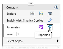
| Properties | Right-click the Constant block, and then click the Properties button
|
| Help | Right-click the Constant block, and then click the Open help documentation button
|
| Copy Path | Right-click the Constant block, click the arrow |
Top Model Canvas Context Menu
| R2025b Context Menu Option | Option in R2026a |
|---|---|
| Explore | Right-click the model canvas, and then click the Open in Model Explorer button
|
| Undo | Right-click the model canvas, click the arrow |
| Redo | Right-click the model canvas, click the arrow |
| Paste | Right-click the model canvas, and then click the Paste button |
| Paste Duplicate Inport | Right-click the model canvas, click the arrow |
| Select All | Right-click the model canvas and select Select All. |
| Find Referenced Variables | Right-click the model canvas, and then click the Referenced Variables button
|
| Test Harness > Create for Model | Right-click the model canvas. To add the Simulink Test app options to the menu, point to
Select Apps and click the Simulink Test button
|
| Test Harness > Import for Model | Right-click the model canvas. To add the Simulink Test app options to the menu, point to
Select Apps and click the Simulink Test button
|
| Test Harness > Manage Test Harnesses | Right-click the model canvas. To add the Simulink Test app options to the menu, point to
Select Apps and click the Simulink Test button
|
| Observers > Go to Observer Reference block | Right-click the model canvas. To add the Simulink Test app options to the menu, point to
Select Apps and click the Simulink Test button
|
| Observers > Add Observer Reference here | Right-click the model canvas. To add the Simulink Test app options to the menu, point to
Select Apps and click the Simulink Test button
|
| Observers > Add Observer Port here | Right-click the model canvas. To add the Simulink Test app options to the menu, point to
Select Apps and click the Simulink Test button
|
| Remove Highlighting | Right-click the model canvas and select Remove Highlighting. |
| Update Diagram | Right-click the model canvas, and then click the Update Model button
|
| Mask > Create System Mask | Right-click the model canvas and select System Mask > Create System Mask. |
| Canvas Color | Right-click the model canvas, and then click the arrow |
| Animation Speed | In the Simulink Toolstrip, on the Debug tab, set Animation speed to Fast, Medium, Slow or None. |
| Sample Time Display > All | Right-click the model canvas and select Information Overlays. Then, select all overlays under Sample Time. |
| Sample Time Display > Annotations | Right-click the model canvas and select Information Overlays. Under Sample Time, select Text. |
| Sample Time Display > Colors | Right-click the model canvas and select Information Overlays. Under Sample Time, select Colors. |
| Sample Time Display > Off | Right-click the model canvas and select Information Overlays. Then, clear all overlays under Sample Time. |
| Sample Time Display > Timing Legend | Right-click the model canvas and select Information Overlays. Under Sample Time, select Timing Legend. |
| Other Displays > Blocks > Block I/O Mismatch for Referenced Models | Right-click the model canvas and select Information Overlays. Under Blocks, select Ref. Model I/O Mismatch. |
| Other Displays > Blocks > Block Version for Referenced Models | Right-click the model canvas and select Information Overlays. Under Blocks, select Ref. Model Version. |
| Other Displays > Blocks > Sorted Execution Order | Right-click the model canvas and select Information Overlays. Under Blocks, select Execution Order. |
| Other Displays > Blocks > Variant Conditions | Right-click the model canvas and select Information Overlays. Under Blocks, select Variant Conditions. |
| Other Displays > Blocks > Tool Tip Options > Block Name | Right-click the model canvas and select Information Overlays. Under Blocks, select Name in Tooltip. |
| Other Displays > Blocks > Tool Tip Options > Parameter Names & Values | Right-click the model canvas and select Information Overlays. Under Blocks, select Parameters in Tooltip. |
| Other Displays > Blocks > Tool Tip Options > Description | Right-click the model canvas and select Information Overlays. Under Blocks, select Description in Tooltip. |
| Other Displays > Signals & Ports > Signal Dimensions | Right-click the model canvas and select Information Overlays. Under Signals, select Signal Dimensions. |
| Other Displays > Signals & Ports > Wide Nonscalar Lines | Right-click the model canvas and select Information Overlays. Under Signals, select Nonscalar Signals. |
| Other Displays > Signals & Ports > Port Data Types | Right-click the model canvas and select Information Overlays. Under Ports, select Base Data Types, Alias Data Types, or both. |
| Other Displays > Signals & Ports > Port Data Type Display Format | Right-click the model canvas and select Information Overlays. Under Ports, select Base Data Types, Alias Data Types, or both. |
| Other Displays > Signals & Ports > Port Units | Right-click the model canvas and select Information Overlays. Under Ports, select Units. |
| Other Displays > Signals & Ports > Propagated Signal Labels | Right-click the model canvas and select Information Overlays. Under Signals, select Propagated Signal Labels. |
| Other Displays > Signals & Ports > Design Ranges | Right-click the model canvas and select Information Overlays. Under Signals, select Signal Data Ranges. |
| Other Displays > Signals & Ports > Signal to Object Resolution Indicator | Right-click the model canvas and select Information Overlays. Under Signals, select Signal Resolves to Object. |
| Other Displays > Signals & Ports > Storage Class | In the Simulink Toolstrip, on the Apps tab, in the apps gallery, select the Embedded Coder or Simulink Coder app. In the toolstrip, on the C Code tab, expand Code Interface and select Storage Class Indicator. |
| Other Displays > Signals & Ports > Testpoint & Logging Indicators | Right-click the model canvas and select Information Overlays. Under Signal Badges, select Test Point. |
| Other Displays > Signals & Ports > Viewer Indicator | Right-click the model canvas and select Information Overlays. Under Signal Badges, select Logging & Viewers. |
| Other Displays > Signals & Ports > Linearization Indicators | In the Simulink Toolstrip, on the Debug tab, expand Information Overlays, and under Signal Badges, select Linearization Indicators. |
| Other Displays > Signals & Ports > Hidden Rate Transition Block Indicators | Right-click the model canvas and select Information Overlays. Under Sample Time, select Automatic Rate Transitions. |
| Requirements at This Level > Link to Selection in MATLAB Editor | Right-click the model canvas. To add the Requirements Manager app options to the menu, point
to Select Apps and click the Requirements Manager button
|
| Requirements at This Level > Link to Current Test Case | Right-click the model canvas. To add the Requirements Manager app options to the menu, point
to Select Apps and click the Requirements Manager button
|
| Requirements at This Level > Link to Current Safety Manager selection | Right-click the model canvas. To add the Requirements Manager app options to the menu, point
to Select Apps and click the Requirements Manager button
|
| Requirements at This Level > Link to Selection in Word | Right-click the model canvas. To add the Requirements Manager app options to the menu, point
to Select Apps and click the Requirements Manager button
|
| Requirements at This Level > Link to Selection in Excel | Right-click the model canvas. To add the Requirements Manager app options to the menu, point
to Select Apps and click the Requirements Manager button
|
| Requirements at This Level > Select for Linking with Simulink | Right-click the model canvas. To add the Requirements Manager app options to the menu, point
to Select Apps and click the Requirements Manager button
|
| Requirements at This Level > Add Link to Selected Object | Right-click the model canvas. To add the Requirements Manager app options to the menu, point
to Select Apps and click the Requirements Manager button
|
| Requirements at This Level > Open Outgoing Links dialog | Right-click the model canvas. To add the Requirements Manager app options to the menu, point
to Select Apps and click the Requirements Manager button
|
| Requirements at This Level > Copy URL to Clipboard | Right-click the model canvas. To add the Requirements Manager app options to the menu, point
to Select Apps and click the Requirements Manager button
|
| Coverage > Open Results Explorer | Right-click the model canvas. To add the Coverage Analyzer app options to the menu, point to
Select Apps and click the Coverage Analyzer button
|
| Coverage > Settings | Right-click the model canvas. To add the Coverage Analyzer app options to the menu, point to
Select Apps and click the Coverage Analyzer button
|
| Model Advisor > Open Model Advisor Exclusion Editor | Right-click a block. To add the Model Advisor app options to the menu, point to Select Apps and click the Model Advisor button |
| Metrics Dashboard | This option is no longer available in the context menu. To access the Metrics Dashboard, in the Simulink Toolstrip, on the Apps tab, in the apps gallery, select the Metrics Dashboard app. |
| Fixed-Point Tool | Right-click the model canvas. Point to Select Apps and click the Fixed-Point Tool button |
| Model Configuration Parameters | Right-click the model canvas, and then click the Model Settings button
|
| Model Properties | Right-click the model canvas, and then click the Model Properties button
|
| Help | Right-click the model canvas, and then click the Open help documentation button
|
Signal Line Context Menu
| R2025b Context Menu Option | Option in R2026a |
|---|---|
| Cut | Right-click the signal line, and then click the Cut button |
| Copy | Right-click the signal line, and then click the Copy button |
| Paste | Right-click the signal line, and then click the Paste button |
| Observers > Observe selected signals > New Observer | Right-click the signal line. To add the Simulink Test app options to the menu, point to
Select Apps and click the Simulink Test button
|
| Observers > Observe selected signals > Name of an existing observer | Right-click the signal line. To add the Simulink Test app options to the menu, point to
Select Apps and click the Simulink Test button
|
| Observers > Go to associated Observer Ports | Right-click the signal line. To add the Simulink Test app options to the menu, point to
Select Apps and click the Simulink Test button
|
| Highlight Signal to Source | Right-click the signal line, and then click the Trace to Source button
|
| Highlight Signal to Destination | Right-click the signal line, and then click the Trace to Destination button
|
| Remove Highlighting | Right-click the signal line, and then click the Remove Trace button
|
| Arrange Automatically | Right-click the signal line, click the arrow |
| Add Breakpoint | Right-click the signal line, and then click the Add Breakpoint button
|
| Show Port Value Label On Selected Signal | Right-click the signal line, and then click the Show port value label button
|
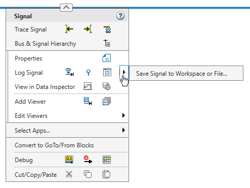
| Log Selected Signals | Right-click the signal line, and then click the Log Signals button
|
| Stop Logging Selected Signals | Right-click the signal line, and then clear the Log Signals button |
| Viewers & Generators Manager | Right-click the signal line, and then click the Viewers Manager button
|
| Open Viewer | Right-click the signal line. Pause on Edit Viewer. Under Selected Viewer, select the viewer you want to open. Then, under Viewer Actions, select Open. |
| Create & Connect Viewer > Simulink > Scope | Right-click the signal line, then click the Add Viewer button |
| Create & Connect Viewer > Communications > Constellation Diagram | Right-click the signal line, then click the Add Viewer button |
| Create & Connect Viewer > Communications > Eye Diagram | Right-click the signal line, then click the Add Viewer button |
| Create & Connect Viewer > DSP > Array Plot | Right-click the signal line, then click the Add Viewer button |
| Create & Connect Viewer > DSP > Scope | Right-click the signal line, then click the Add Viewer button |
| Create & Connect Viewer > DSP > Sprectrum Analyzer | Right-click the signal line, then click the Add Viewer button |
| Create & Connect Viewer > Computer Vision > To Video Display | Right-click the signal line, then click the Add Viewer button |
| Create & Connect Viewer > HDL Verifier for use with Cadence Incisive > To VCD File | Right-click the signal line, then click the Add Viewer button |
| Create & Connect Viewer > HDL Verifier for use with Mentor Graphics ModelSim > To VCD File | Right-click the signal line, then click the Add Viewer button |
| Connect To Viewer | Right-click the signal line. Pause on Edit Viewer. Under Selected Viewer, select the viewer to which you want to connect. Then, under Viewer Actions, select Connect. |
| Disconnect Viewer | Right-click the signal line. Pause on Edit Viewer. Under Selected Viewer, select the viewer you want to disconnect. Then, under Viewer Actions, select Disconnect. |
| Delete Viewer | Right-click the signal line. Pause on Edit Viewer. Under Selected Viewer, select the viewer you want to delete. Then, under Viewer Actions, select Delete. |
| Linear Analysis Points > Linearization Manager | Right-click the signal line. To open the Linearization Manager app, point to Select Apps and click the Linearization Manager button |
| Linear Analysis Points > Open-loop Input | Right-click the signal line. To add the Linearization Manager app options to the menu, point
to Select Apps and click the Linearization Manager button
|
| Linear Analysis Points > Open-loop Output | Right-click the signal line. To add the Linearization Manager app options to the menu, point
to Select Apps and click the Linearization Manager button
|
| Linear Analysis Points > Loop Transfer | Right-click the signal line. To add the Linearization Manager app options to the menu, point
to Select Apps and click the Linearization Manager button
|
| Linear Analysis Points > Loop Break | Right-click the signal line. To add the Linearization Manager app options to the menu, point
to Select Apps and click the Linearization Manager button
|
| Linear Analysis Points > Input Perturbation | Right-click the signal line. To add the Linearization Manager app options to the menu, point
to Select Apps and click the Linearization Manager button
|
| Linear Analysis Points > Output Measurement | Right-click the signal line. To add the Linearization Manager app options to the menu, point
to Select Apps and click the Linearization Manager button
|
| Linear Analysis Points > Sensitivity | Right-click the signal line. To add the Linearization Manager app options to the menu, point
to Select Apps and click the Linearization Manager button
|
| Linear Analysis Points > Complementary Sensitivity | Right-click the signal line. To add the Linearization Manager app options to the menu, point
to Select Apps and click the Linearization Manager button
|
| Linear Analysis Points > Trim Output Constraint | Right-click the signal line. To add the Linearization Manager app options to the menu, point
to Select Apps and click the Linearization Manager button
|
| Linear Analysis Points > Help Me Select | In the help documentation, see Specify Portion of Model to Linearize (Simulink Control Design). |
| Signal Hierarchy | Right-click the signal line, and then click the Signal Hierarchy button
|
| Properties | Right-click the signal line, and then click the Properties button |
Text Annotation Context Menu
| R2025b Context Menu Option | Option in R2026a |
|---|---|
| Cut | Right-click the annotation, and then click the Cut button |
| Copy | Right-click the annotation, and then click the Copy button |
| Edit Text | Right-click the annotation and select Edit Text. |
| Format > Arrange Automatically | Right-click the annotation, click the arrow |
| Format > Foreground Color | Right-click the annotation, and then click the arrow |
| Format > Background Color | Right-click the annotation, and then click the arrow |
| Format > Bring to Front | Select the annotation. In the Simulink Toolstrip, on the Format tab, click the Bring to front button |
| Format > Send to Back | Select the annotation. In the Simulink Toolstrip, on the Format tab, click the Send to back button |
| Text Alignment | Right-click the annotation, and then click the Properties button Left, Center, or Right. |
| Enable TeX Commands | Right-click the annotation, and then click the Properties button |
| Requirements > Link to Selection in MATLAB Editor | Right-click the annotation. To add the Requirements Manager app options to the menu, point to
Select Apps and click the Requirements Manager button
|
| Requirements > Link to Selection in Model Explorer | Right-click the annotation. To add the Requirements Manager app options to the menu, point to
Select Apps and click the Requirements Manager button
|
| Requirements > Link to Current Test Case | Right-click the annotation. To add the Requirements Manager app options to the menu, point to
Select Apps and click the Requirements Manager button
|
| Requirements > Link to Selection in Safety Analysis Manager | Right-click the annotation. To add the Requirements Manager app options to the menu, point to
Select Apps and click the Requirements Manager button
|
| Requirements > Link to Selection in Word | Right-click the annotation. To add the Requirements Manager app options to the menu, point to
Select Apps and click the Requirements Manager button
|
| Requirements > Link to Selection in Excel | Right-click the annotation. To add the Requirements Manager app options to the menu, point to
Select Apps and click the Requirements Manager button
|
| Requirements > Select for Linking with Simulink | Right-click the annotation. To add the Requirements Manager app options to the menu, point to
Select Apps and click the Requirements Manager button
|
| Requirements > Add Link to Selected Object(s) | Right-click the annotation. To add the Requirements Manager app options to the menu, point to
Select Apps and click the Requirements Manager button
|
| Requirements > Open Outgoing Links dialog | Right-click the annotation. To add the Requirements Manager app options to the menu, point to
Select Apps and click the Requirements Manager button
|
| Requirements > Copy URL to Clipboard | Right-click the annotation. To add the Requirements Manager app options to the menu, point to
Select Apps and click the Requirements Manager button
|
| Properties | Right-click the annotation, and then click the Properties button |
| Convert to Markup | Right-click the annotation, and under Visibility, select Markup. |
| Convert to Annotation | Right-click the annotation, and under Visibility, select Annotation. |