Enable and Configure Raspberry Pi for SPI and CAN Communication Using MCP2515 CAN Controller
Follow these steps to set up the MCP2515 CAN interface on a Raspberry Pi® board.
Hardware Requirements
You need these components to set up CAN bus communication using Raspberry Pi:
Raspberry Pi board
MCP2515 CAN controller module
SI65HVD230 CAN transceiver
Jumper wires
CAN bus cables
Hardware Connections
Use the connections specified in this table to connect a Raspberry Pi board to a CAN bus using the MCP2515 CAN controller and the SI65HVD230 CAN transceiver.
| Raspberry Pi | MCP2515 CAN Controller | SI65HVD230 CAN Transceiver | CAN Bus |
|---|---|---|---|
VCC | VCC | VCC | N/A |
GND | GND | GND | |
GPIO 8 (CE0) | CS | N/A | |
GPIO 11 (SCLK) | SCL | ||
GPIO 10 (MOSI) | SI | ||
GPIO 9 (MISO) | SO | ||
GPIO 25 | INT | ||
| N/A | TXD | D (Driver Input) | |
RXD | R (Receiver Output) | ||
| N/A | CANH | CANH | |
CANL | CANL |
Enable SPI Interface for CAN Communication
Raspberry Pi uses the serial peripheral interface (SPI) protocol to communicate with the CAN controller. Follow these steps to enable SPI on your Raspberry Pi, which, in turn, enables communication over the CAN bus.
Open the Raspberry Pi terminal.
Enter the following command to access the configuration interface.
sudo raspi-config
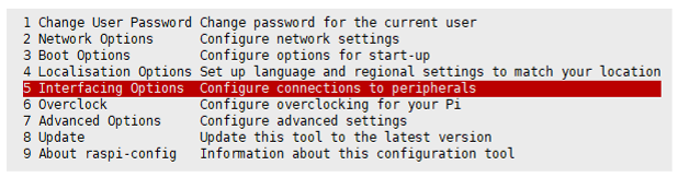
Use the arrow keys to select Interfacing Options and press Enter.
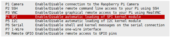
Select SPI from the list and press Enter.
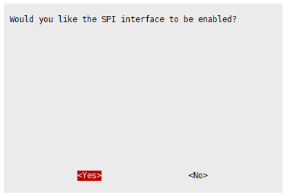
Select Yes to enable the SPI interface.
To apply the changes, reboot your Raspberry Pi.
sudo reboot
Verify if the SPI module is loaded on your Raspberry Pi.
lsmod | grep spi
For example, when you execute this command, the terminal lists
spi_bcm2835SPI driver.Verify if that SPI devices are available.
ls /dev/spi*
For example, when you execute this command, the terminal lists
/dev/spidev0.0and/dev/spidev0.1.
Set Up MCP2515 CAN Controller with SocketCAN
Modify the hardware settings in the config.txt file to enable the
SPI interface and configure the MCP2515 CAN controller. Make sure to set up the hardware
connections before you begin modifying the file.
Open the Raspberry Pi terminal.
Open the
config.txtfile. Note that the location of the file varies depending on the operating system running on your Raspberry Pi board. This table lists the file paths on the Bullseye and Bookworm operating systems and the commands to use to open theconfigtext file.Operating System Path to config.txtfileCommand to execute on Raspberry Pi terminal Bullseye /boot/firmware/config.txtsudo nano /boot/firmware/config.txt
Bookworm /boot/config.txtsudo nano /boot/config.txt
Enable SPI interface.
dtparam=spi=on
Individually configure the CAN controllers. For this example, configure the can0 and can1 MCP2515 CAN controllers. Set the oscillator frequency for the controllers to 16000000 Hz. Set the interrupt pins
23and25. You can adjust the oscillator frequency, interrupt pins according to your requirements. Refer to the CAN vendor datasheet for more details on the number of CAN controllers supported, the supported oscillator frequency, and the interrupt pins.dtoverlay=mcp2515-can0,oscillator=16000000,interrupt=25 dtoverlay=mcp2515-can1,oscillator=16000000,interrupt=23
Save the file and exit.
To apply the changes, reboot your Raspberry Pi.
sudo reboot
Verify CAN controller initialization.
dmesg | grep spi
Check availability of CAN interface on Raspberry Pi.
ifconfig
For example, when you execute this command, the terminal lists
can0andcan1controllers.
After you have successfully enabled and configured the MCP2515 CAN controller using your Raspberry Pi board, you can now use the CAN Transmit and CAN Receive blocks in a Simulink® model and configure the CAN properties in the Configuration Parameters dialog box.
See Also
SocketCAN | Setup Virtual CAN Interface | CAN Transmit | CAN Receive | CAN properties
Topics
- Transmit and Receive Data Using Raspberry Pi CAN Blocks
- Monitor Engine RPM Using Raspberry Pi CAN Blocks