Track Object Using ROS and Simulink on Raspberry Pi
This example shows how to use Simulink® Support Package for Raspberry Pi® Hardware, ROS Toolbox, and a Raspberry Pi hardware board to track a green colored object. This example also shows how to use the Publish and Subscribe blocks to establish communication between the ROS node deployed on the Raspberry Pi hardware board and the ROS node in Simulink (host computer).
This example uses two Simulink models.
rosberrypi_object_tracking: This Simulink model uses a vision and control algorithm to detect a green colored object. Deploy this model as a ROS node on your Raspberry Pi hardware.rosberrypi_object_tracking_host: This Simulink model uses the ROS Publish and Subscribe blocks to communicate with therosberrypi_object_trackingSimulink model over the ROS network. You run this Simulink model on your host computer.
Required Hardware
Raspberry Pi hardware board
USB camera or Raspberry Pi camera module
Servo motor and a camera mount
Connecting wires
Hardware Setup
Power the Raspberry Pi hardware board.
Connect the servo motor to the Raspberry Pi board using the connecting wires. Connect the GND and VCC pins. Connect the servo motor signal pin to GPIO pin 18 of the Raspberry Pi hardware board.
Mount the camera on top of the servo motor with a double-sided tape or some other adhesive. This example uses a USB webcam.
Install and Set Up ROS on Raspberry Pi
Install ROS Melodic on your Raspberry Pi hardware board. For more information, see Install ROS Melodic on Raspberry Pi. To initialize the ROS master on your host computer, in the MATLAB® Command Window, execute this command.
rosinit('NodeHost',<IP address of your computer>)Configure rosberrypi_object_tracking Simulink Model and Calibrate Parameters
Deploy the rosberrypi_object_tracking Simulink Model that uses a vision and control algorithm on the Raspberry Pi board.
Open the rosberrypi_object_tracking Simulink model.

In the Configuration Parameters dialog box, go to Target hardware resources > Build options, and click Edit. Configure these parameters in the Connect to ROS device dialog box.
Enter your Raspberry Pi Device address, Username, and Password.
Set ROS folder to
/opt/ros/melodic.Set Catkin workspace to
/home/pi/catkin_ws.
Image from Raspberry Pi Camera and Subscribe to RGB Thresholds
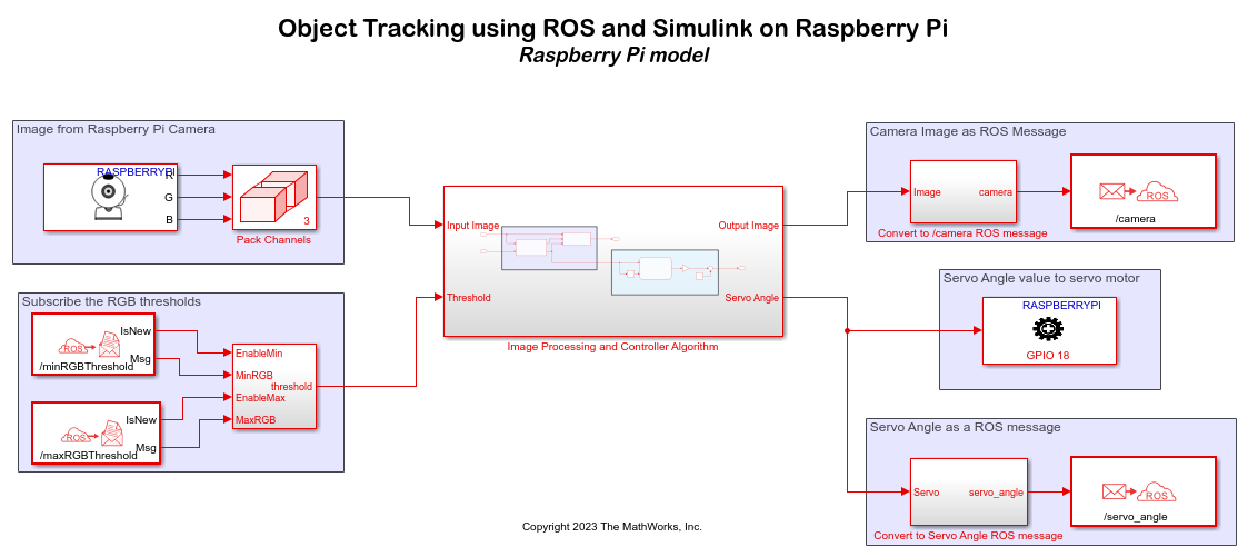
The Raspberry Pi V4L2 Video Capture block captures the live video from the camera and outputs a moving colorbar image along with the R, G, and B components. The Algorithm subsystem revives this image as an input.
The Subscribe blocks in the Subscribe the RGB thresholds area subscribes to the /minRGBThreshold and /maxRGBThreshold topics to receive the minimum and maximum RGB threshold values set in the Publish blocks in the rosberrypi_object_tracking_host Simulink model.
Image Processing and Controller Algorithm
The input image from the camera feed and the RGB threshold values are the input to the Image Processing and Controller Algorithm subsystem. The Blob Detection subsystem uses the vision.BlobAnalysis (Computer Vision Toolbox) function. The output of this subsystem is the centroid coordinates of the blob object. In the Vision Results Processing subsystem, the Draw Markers (Computer Vision Toolbox) block draws circular markers around the blob object. The subsystem then converts the output image to a ROS message and publishes the message over the ROS network to the /camera topic. The Tracking Controller is designed using a Stateflow® diagram and has three states.
Tracking: Track the object once identified
Waiting: Wait for the object to be in the frame
Seeking: Seek the object
The Tracking Controller subsystem calculates the servo angle and outputs the angle as a ROS message.
Camera Image as ROS Message, Servo Angle as ROS Message, and Servo Angle Value to Servo Motor
The output servo angle and the output camera feed from the Tracking Controller subsystem is published over the ROS network to the /servo_angle and /camera topics, respectively. The Standard Servo Write block receives the servo angle value from the motor. Verify that you have specified the number of the same pin in the Standard Servo Write block as the pin to which you have connected to the servo motor to the Raspberry Pi board.
Configure rosberrypi_object_tracking_host Simulink Model and Calibrate Parameter
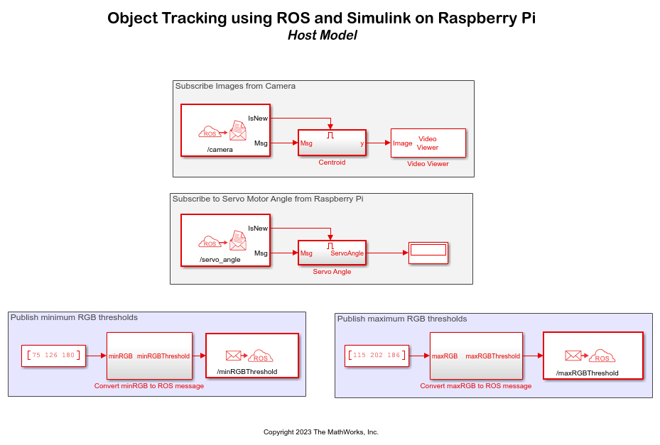
The rosberrypi_object_tracking_host Simulink model uses the Publish and Subscribe blocks to establish communication between the ROS nodes over the ROS network.
Open the rosberrypi_object_tracking_host Simulink model.

In the Subscribe Images from Camera area, the Subscribe block subscribes to the /camera topic to receive the camera feed over the ROS network. The Reshape block changes the dimensions of the extracted data from the camera feed and convert it into a signal represented by an M-by_N_-by-3 matrix. The Video Viewer (Computer Vision Toolbox) block displays the camera feed output.
Similarly, in the Subscribe to Servo Motor Angle from Raspberry Pi area, the Subscribe block subscribes to the servo_angle topic to receive the rotation angle from the servo motor over the ROS network and displays the angle in the Display block.
You can set the range of RGB threshold values in the Constant blocks in the Publish minimum RGB thresholds and Publish maximum RGB thresholds areas. The Publish blocks in the Simulink model publishes these minimum and maximum RGB threshold values to the topics /minRGBThreshold and /maxRGBThreshold, respectively, over the ROS network. The Subscribe blocks in the rosberrypi_object_tracking Simulink model subscribe to these topics to receive the threshold values over the ROS network.
Note: On account of the sensitivity of your camera to ambient light and brightness, you might need to adjust the minimum and maximum RGB threshold values in the Simulink model for the Raspberry Pi to detect a green colored object in the vicinity of the camera.
Deploy rosberrypi_object_tracking Simulink Model on Raspberry Pi
In the ROS tab of the rosberrypi_object_tracking Simulink model, click Build & Run to deploy the Simulink model on your Raspberry Pi hardware board.
Run rosberrypi_object_tracking_host Simulink Model on Host Computer
In the Simulation tab of the rosberrypi_object_tracking_host Simulink model, click Run to run the Simulink model on your host computer. Place a green colored object in front of the camera. Observe the live feed from the camera and the servo angle, respectively, in the Video Viewer and the Display blocks. To track any other color, change the minimum and maximum RGB threshold values in the Simulink model and run the model again.