Set Up a Wi-Fi UDP Connection with Connected IO in Simulink
Perform these steps to setup and configure Wi-Fi® UDP connection with Connected IO in your Simulink® model.
Open a new Simulink model.
Insert a WiFi UDP Send block and establish a connection with a Constant block.
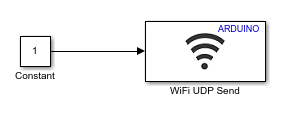
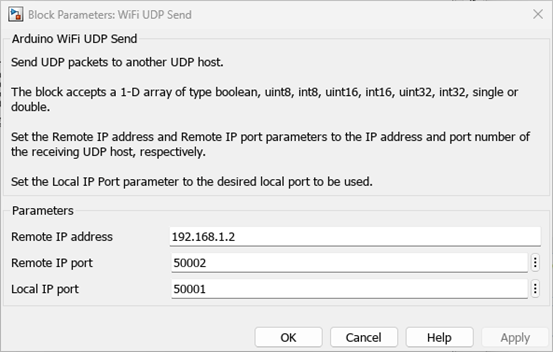
Double-click the WiFi UDP Send block to open the Block Parameters dialog box. Modify the default Local IP port setting to your preferred value.
In the Simulink model, on the Modeling tab, click Model Settings to open the Configuration Parameters dialog box.
In the Configuration Parameters dialog box, select the appropriate hardware from the
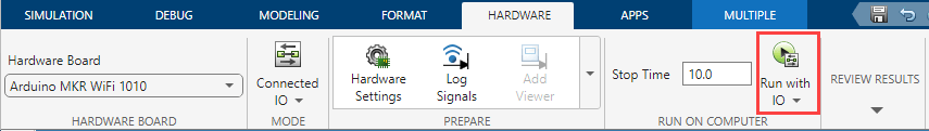
Hardware Boarddrop-down list, such as Arduino® MKR WiFi 1010.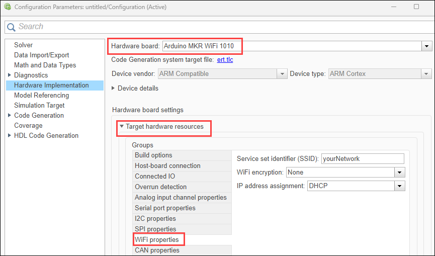
Navigate to Target hardware resources > WiFi properties and configure the Wi-Fi properties by specifying the SSID and Wi-Fi encryption settings according to your network requirements.
On the Hardware tab of the Simulink model, navigate to the Mode section. Select Connected IO and initiate the simulation by clicking Run with IO.
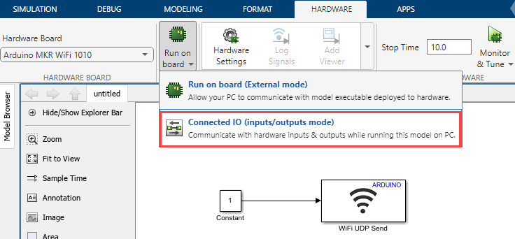
Check the diagnostic viewer to view the IP address assigned to the target.
These steps ensure the correct setup and configuration for using Wi-Fi TCP/IP communication in your Simulink model.
Run the host model to receive data from the target model
Open a new Simulink model.
Add a UDP Receive block and connect it to a Display block.
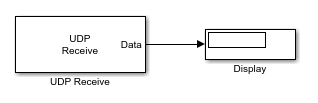
Double-click the UDP Receive block. Ensure that the IP address is same as the IP address displayed in the diagnostic viewer of Connected IO mode. Also, the port must be same as the value specified in the WiFi UDP block.
In the Simulation tab of the Simulink model, click Run. Observe the Scope to confirm that the target hardware is successfully transmitting the data, which includes a ramp signal and a pulse.