Get Started with IO Device Builder
System Requirements
To use the IO Device Builder, you need the following MathWorks® software:
Open IO Device Builder
Note
By default, communication libraries such as SPI, I2C, and Servo are included. For information on adding other libraries, see Working with Arduino Libraries in IO Device Builder.
The IO Device Builder app supports only Monitor & Tune (External mode) and Build, Deploy & Start options. Connected IO is not supported.
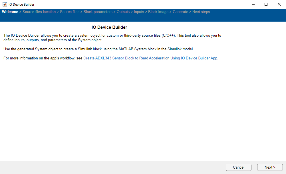
To open the IO Device Builder app, follow these steps.
Start MATLAB® and then open / create a Simulink® model.
In the Simulink model, navigate to Modeling > Model Settings.
In the Configuration Parameters dialog box, click Hardware Implementation and then select an Arduino board.
On the Hardware tab of the Simulink toolstrip, in the Prepare section, under Design, choose
IO Device
                        Builder
.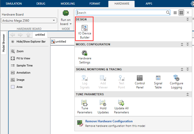
Click Next.
Select Working Directory and Add Third-party Source Files
Once the Source files location page loads, click Select to select the working directory.
The specified directory is where you can find the generated System object™, along with the corresponding cpp and h files, as well as the model.
By default, communication libraries such as SPI, I2C, and Servo are included. For information on adding other libraries, see Working with Arduino Libraries in IO Device Builder.

Click Add folder to add the third-party source files you downloaded.
Note
Third-party source files can be downloaded from the internet. For example, to add ADXL345 files, download the source files for ADXL345 sensor.
Click Next.
Source Files
Once the Source Files select the required source files and then click Next to continue.

Add Block Name, Block Description, and Add Block Parameters
In the Block parameters page, specify a name, add description, and add the required parameters for the block.

Specify a name for the block in Block Name textbox.
Enter a description for the block in Block description textbox.
Add the required parameters for the block using Add and Remove buttons. Use Move up and Move down buttons to move the selected parameters up / down in the list.
Note
To determine the block parameters, open the INO file and search for the parameters. For example, for the ADXL345 accelerometer sensor, you can add the accelerometer range parameter from the Adafruit® GitHub® files.
Click Next to move to the next page.
Add Outputs for the Block
In the Outputs page, add the required output ports for the block.

After adding the required output ports, click Next to move to the next page.
Add Inputs for the Block
In the Inputs page, add the required input ports for the block.
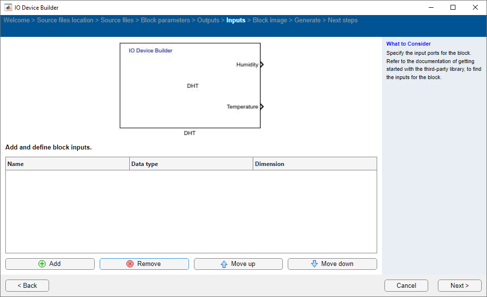
After adding the required input ports, click Next to move to the next page.
Preview Block Image
In the Preview page, a preview image of the block is shown along with the outputs and inputs you added.
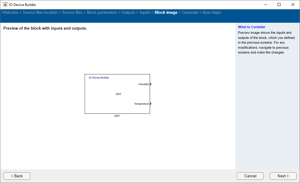
Click Next to move to the next page.
Generate System Object Files
Choose the Select to generate a C++ driver option, if you want to generate a C++ file. Click Generate to generate the System object files.

Next Steps
On the Next Steps page, the files generated are shown and the next steps to be performed are displayed. The generated files are created in a directory. This directory also includes a Dependencies folder that contains selected third-party source files. Simply copy these files and the folder to your desired location and integrate them into your Simulink project.

Click Finish.
The generated cpp file opens automatically.
Modify the generated cpp files step and setup function with the respective function calls from the third-party source files.
Then open the generated model and navigate to Modeling > Model Settings and in the Configuration Parameters dialog box, click Hardware Implementation and then select an Arduino® board and do the necessary modifications.
Note
Before performing Monitor and Tune action, perform these steps to set the default parameter behavior to tunable.
In the Simulink model, press Ctrl+E. The Configuration Parameters dialog box appears.
Navigate to Code Generation > Optimization and ensure that
Tunableis selected for Default parameter behavior.