Communicate with Arduino Hardware Using XCP-Based Simulation
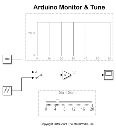
This example shows how to use the Simulink® Support Package for Arduino® Hardware to tune the parameters and monitor the signals of an algorithm running on the Arduino Mega 2560 board using XCP-based simulation.
Supported Hardware
All Arduino boards as listed in the Supported Hardware section of Arduino Support from Simulink.
Description
The provided model is preconfigured for Arduino Mega 2560 and can be run on any of the boards listed in the Supported Hardware section. To select a hardware board, follow the steps in the Configuring the Model for the Arduino Mega 2560 Board section.
Simulink Support Package for Arduino Hardware enables you to monitor and tune algorithms running on Arduino board from the same Simulink models from which you developed the algorithms.
In this example, you will learn how to tune and monitor the algorithm in real time. When you are developing algorithms, it is often necessary to determine appropriate values of critical algorithm parameters in an iterative fashion. For example, a surveillance algorithm that measures motion energy in a room may use a threshold to detect an intruder in the presence of ambient noise. If the threshold value is set too low, the algorithm may erroneously interpret any movement as an intruder. If the threshold value is set too high, the algorithm may not be able to detect any movement at all. In such cases, you can try different threshold values until the desired algorithm performance is reached. This iterative process is called parameter tuning.
The Monitor & Tune feature enables you to accelerate the process of parameter tuning by letting you change certain parameter values while the model is running on the target hardware, without stopping the simulation. When you change the parameter values from within Simulink, the modified parameter values are communicated to the target hardware immediately. The effects of the parameter tuning activity can be monitored by viewing algorithm signals on scopes or displays in Simulink.
Simulink provides these additional features for the targets that support XCP:
Dashboard objects such as Slider and Dashboard Scope. For more information, see Dashboard.
Simulation Data Inspector for visualizing the logged signals. For more information, see Simulation Data Inspector.
Prerequisites
Before you start with this example, we recommend you complete the Get Started with Arduino Hardware example.
Required Hardware
Arduino Mega 2560
Configure Simulink Model for Arduino Mega 2560 Hardware Board
1. Open the arduino_xcp_externalmode Simulink model.

2. In the Modeling tab, select Model Settings to open the Configuration Parameters dialog box.
3. Go to Hardware Implementation > Hardware board and select the Arduino board. Do not change any other settings.
4. Click OK.
5. This example model has one signal selected for logging. To select additional signals, right-click the required signal and select the Log Selected Signals option.
Run Simulink Model
In the Configuration Parameters dialog box, go to Hardware Implementation > External mode > Communication Interface and ensure that the communication interface is set to
XCP on Serial, before performing Monitor and Tune action.Open the arduino_xcp_externalmode model.
On the Hardware tab of the Simulink model, in the Mode section, select Run on board and then click Monitor & Tune. The model now runs in real-time on the target hardware.