DSP System Toolbox Array Plot Block and Mobile Apps
Using the DSP System Toolbox™ Array Plot (DSP System Toolbox) block with the Simulink® Support Package for Android® Devices, you can:
Display the array plot on the device screen when you build, load, and run the model on your mobile device.
Show a real-time display of raw or processed sensor data on your device screen.
Display multiple signals from various sources on a single array plot display.
Include multiple array plot displays to group related data signals.
Match your preferences by customizing the appearance of the array plot.
Add DSP System Toolbox Array Plot to App
Create a Simulink model.
In the Modeling tab of the toolstrip, select Model Settings to open the Configuration Parameters dialog box.
Select the Hardware Implementation pane and from the Hardware board parameter list, select
Android Device. Click OK.Open the Simulink Library Browser. From the Simulink > Sources library, add a Random Number block to your model.
From the DSP System Toolbox > Statistics library, add Histogram (DSP System Toolbox) block to your model.
From the DSP System Toolbox > Sinks library, add a Array Plot (DSP System Toolbox) block to your model.
In the model, connect the three blocks as shown.

In the Histogram block, set the properties as follows.
Set Lower limit of histogram to
-5.0.Set Lower limit of histogram to
5.0.Set Number of bins to
101.Set Find the histogram over to
Entire Input.Check Normalized.
Check Running histogram.
In the Random Number block, set the Sample time to
0.01. Click OK.On the Simulation tab of the model, click Run.

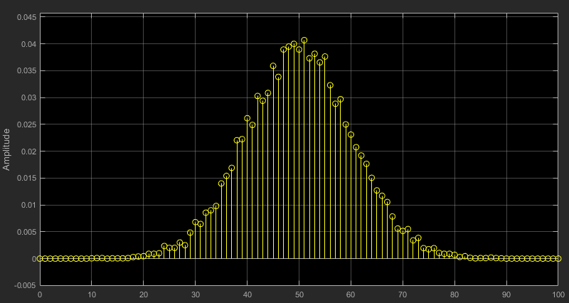
To open the Array Plot viewer and see the histogram of the signal, double-click the Array Plot block. The histogram takes the form of a normal distribution curve.
On the Hardware tab of the Simulink model, in the Mode section, select
Run on boardand then select Build, Deploy & Start.

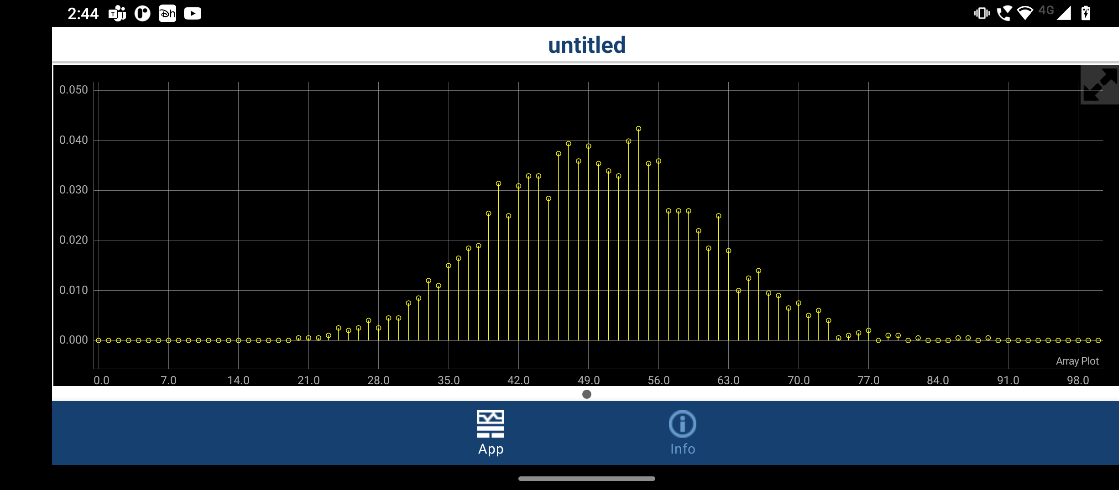
When the app starts running on your device, you can see the equivalent array plot display on your device screen.
Array Plot Displays on App
Multiple Array Plots or Scopes
In a model with multiple Array Plot (DSP System Toolbox) or Scope blocks, the array plot and scope displays in your app are shown on multiple pages.
Below the array plot displays, a page indicator widget is automatically generated to show the current array plot selection. Click to the right or left of the page indicator widget to cycle between the available array plot displays.

Note
If a model contains a Camera or a Video Display block, Scope block, and Array Plot (DSP System Toolbox) block, then the camera or video display is first page, followed by the other scope or array plot displays.
Default and Full Screen Display
On the device screen, each array plot display provides a default and a full screen viewing mode. The default view splits the app display into two parts. The left half shows the array plot displays and the right half shows the UI widgets, including the Button, Slider, and Data Display blocks, in your model. The full screen view expands the array plot display to fill the device screen, allowing a more detailed inspection of signals. To toggle between the two views, click the arrow button in the top right corner of the array plot display on your device screen.

Interaction with the Display
On the device screen, you can adjust an array plot display using typical interactive gestures. By tapping and dragging your finger across the screen, you can move the display axes horizontally and vertically. By tapping two fingers on the screen and moving them closer or farther apart, you can zoom in and out of the axes.
Array Plot Style
To modify the appearance of the array plot in your app, you can use a subset of the style properties available to the scope on your development computer.
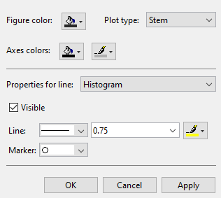
To open the Style dialog box from the array plot display box, click View > Style.
For more information on general configuration properties, see the Array Plot (DSP System Toolbox) block.

- Plot type
The styles of plot used to display the signal:
Line
Stairs
Stem
- Axes colors
Select the background color for axes (displays) with the first color palette. Select the ticks, labels, and grid color with the second color palette.
- Line
Select the line style, width, and color. The array plot displayed on the app supports continuous, dotted, and dashed line styles only. All other line style selections automatically default to continuous.
Note
All other array plot style parameters use their default value for the array plot display in the app.
Array Plot Configuration Properties
You can modify the configuration of the array plot properties in your app by using a subset of the configuration properties available to the array plot on your development computer.
To open the Configuration Properties dialog box, in the scope display box, click View > Configuration properties.
For more information on general configuration properties and their default settings, see the Array Plot (DSP System Toolbox) block.

- Sample increment
Specify the spacing between samples along the x-axis as a finite numeric scalar. The input signal is only y-axis data. X-axis data is set automatically based on both the Sample increment and X-offset values. For example, when X-offset is 0 and Sample increment is 1, the x-data for the input signal is set to 0, 1, 2, 3, 4, … . If you set Sample increment to 0.25, the x-axis data becomes 0, 0.25, 0.5, 0.75, 1, … .
- X-offset
Specify the offset to apply to the x-axis, as a numeric scalar. X-axis data is set automatically based on both the Sample increment and X-offset values. The offset represents the first value on the x-axis. For example, when X-offset is 0 and Sample increment is 1, the x-data for the input signal is set to 0, 1, 2, 3, 4, … . If you set X-offset to -3, the x-axis data becomes -3, -2, -1, 0, 1, … .
- Show legend
Show signal legend. The names listed in the legend are the signal names from the model. For signals with multiple channels, a channel index is appended after the signal name.
- Show grid
Show vertical and horizontal grid lines.
- Y-limits (Minimum)
Specify the minimum value of the y-axis, as a real number.
- Y-limits (Maximum)
Specify the maximum value of the y-axis, as a real number.
Note
All other array plot configuration parameters use their default values for the array plot in the generated app.
Limitations
The following limitations apply. These limitations also describe the differences between the array plot behavior while the model is running and when the model builds to the hardware.
After you click Deploy to Hardware to start generating the app, changes made to the configuration properties of the scope are not automatically applied. For the array plot configuration properties to take effect in the app, you must remove the previous generated project. To remove this project, delete the folder
<your model
                        name>_ert_rtw
in your working folder.Layouts or multiple axes within one array plot display are not supported for array plot displays in a generated app.
Array plots are displayed on the app in landscape view only.