Visualize Model Reference Hierarchies
This example shows how to view, explore, and analyze model dependencies using the Dependency Analyzer. It shows how to find referenced models and interact with the dependency graph.
Open Top Model
Open the example. The ModelReferenceHierarchy project defines a model reference hierarchy. The top model in the hierarchy, sldemo_mdlref_depgraph, references multiple other models.
Find Referenced Models
Use the find_mdlrefs
[refMdls, modelBlks] = find_mdlrefs('sldemo_mdlref_depgraph')
find_mdlrefs returns two cell arrays, refMdls and modelBlks. refMdls contains the names of all models that are directly or indirectly referenced by sldemo_mdlref_depgraph. By default, the last element in refMdls is the name of the input model. modelBlks contains block paths for all Model blocks in the top model and all referenced models.
View Model Reference Dependency Graph
To view the dependency graph for the sldemo_mdlref_depgraph model, perform one of these actions to open the Dependency Analyzer for a model:
Use the
depviewfunction.In the Modeling tab, in the Design section, click Dependency Analyzer.
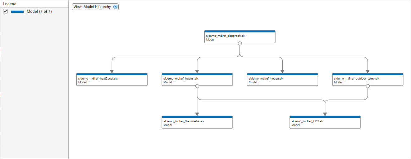
In the dependency graph, the boxes represent Simulink® models. The arrows indicate dependencies. For example, the link from sldemo_mdlref_depgraph to sldemo_mdlref_house indicates that sldemo_mdlref_depgraph references sldemo_mdlref_house. If the model references libraries, subsystems, or protected models, the dependency graph shows them in the hierarchy.
In this view, only one box exists for each model in the graph and at most one arrow exists from one box to another box. The dependency graph does not show if multiple references exist from one model to another model. This view does not show which models are referenced in normal mode and which models are referenced in accelerator mode.
Interact with Dependency Graph
To select a box, click it.
To open the model or library associated with a box, double-click it.
To pan the dependency graph, click and hold the mouse wheel button then drag the mouse.
To zoom in and out, use the mouse wheel.
To center the dependency graph and adjust the zoom so that the dependency graph fills the available space, press the space bar.
View Model Instances Dependency Graph
To view the referenced model instances in the dependency graph, perform one of these actions:
Use
depview('sldemo_mdlref_depgraph','ModelReferenceInstance',true).From the Dependency Analyzer, in the Views section, select Model Instances.

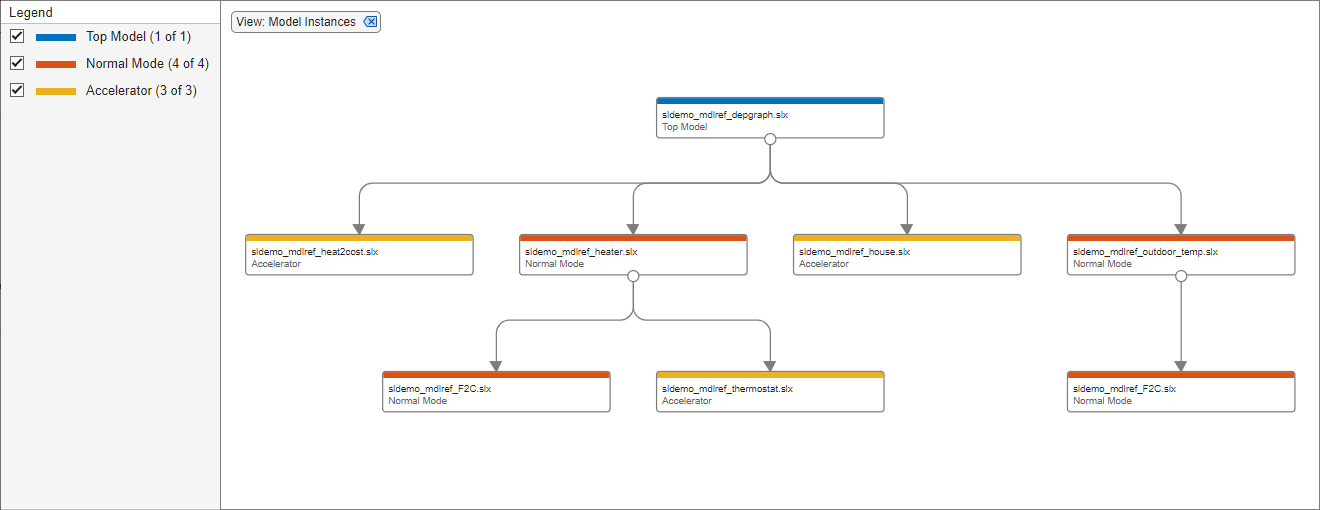
In the instance view, the boxes represent Simulink models. The arrows indicate dependencies. The dependency graph shows when multiple references exist from one model to another model. In the instance view, libraries are not shown.
In this view, two boxes are labeled sldemo_mdlref_F2C because this model is referenced twice, once by sldemo_mdlref_outdoor_temp and once by sldemo_mdlref_heater. The legend provides colors that represent the top model, models referenced in normal mode, and models referenced in accelerator mode.
sldemo_mdlref_heater makes a normal mode reference to sldemo_mdlref_F2C and an accelerator mode reference to sldemo_mdlref_thermostat.
Explore Model Instance Views
Currently, the reference sldemo_mdlref_outdoor_temp makes to sldemo_mdlref_F2C is an accelerator mode reference. Suppose you want to change this reference to be a normal mode reference.
Select the arrow linking
sldemo_mdlref_outdoor_temptosldemo_mdlref_F2C.In the Properties pane on the right, in the dependency table, click
Fahrenheit to Celsius. Simulink opens the modelsldemo_mdlref_outdoor_tempand highlights the Model block namedFahrenheit to Celsius. This Model block referencessldemo_mdlref_F2C.Select the Model block named
Fahrenheit to Celsius.In the Model Block tab, change the Simulation Mode to
Normal.To see this change, go to the dependency graph and click Analyze.

The dependency graph now shows the reference sldemo_mdlref_outdoor_temp makes to sldemo_mdlref_F2C as a Normal Mode (Overridden) reference. Note that sldemo_mdlref_F2C is configured to run in normal mode but its parent, sldemo_mdlref_outdoor_temp, is configured to run in accelerator mode. Normal mode references from models running in accelerator mode are not supported, so sldemo_mdlref_F2C will run in accelerator mode during simulation.
To make this model run in normal mode, you must configure all of its ancestors to run in normal mode.
Select the arrow linking
sldemo_mdlref_depgraphtosldemo_mdlref_outdoor_temp.In the Properties pane on the right, in the dependency table, click
outdoor temp. Simulink opens the modelsldemo_mdlref_depgraphand highlights the Model block namedoutdoor temp. This Model block referencessldemo_mdlref_outdoor_temp.Select the Model block named
outdoor temp.In the Model Block tab, change the Simulation Mode to
Normal. (If there were more accelerator mode ancestors ofsldemo_mdlref_F2C, these would also need to be changed to normal mode references.)To see this change, go to the dependency graph and click Analyze.