Vehicle Electrical and Climate Control Systems
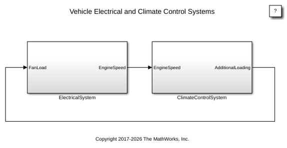
R2026bThis example shows how to model a vehicle climate control system with an electrical system. Use the model to examine the loading effects of the climate control system on the entire vehicle electrical system.
Climate Control System
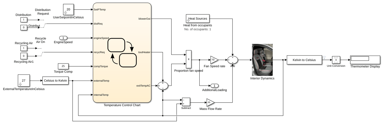
To open the climate control system model, double-click the ClimateControlSystem subsystem. You can specify these settings:
Internal vehicle temperature – Subsystem block named
UserSetpointInCelsiusblock. Enter a value for the temperature.External vehicle temperature – Subsystem block named
ExternalTemperatureInCelsius. Enter a value for the temperature.
The Display block named Thermometer Display provides the temperature reading of a sensor behind the head of the driver. As the model runs when the climate control is active, this reading indicates the temperature the driver feels.
Stateflow Controller
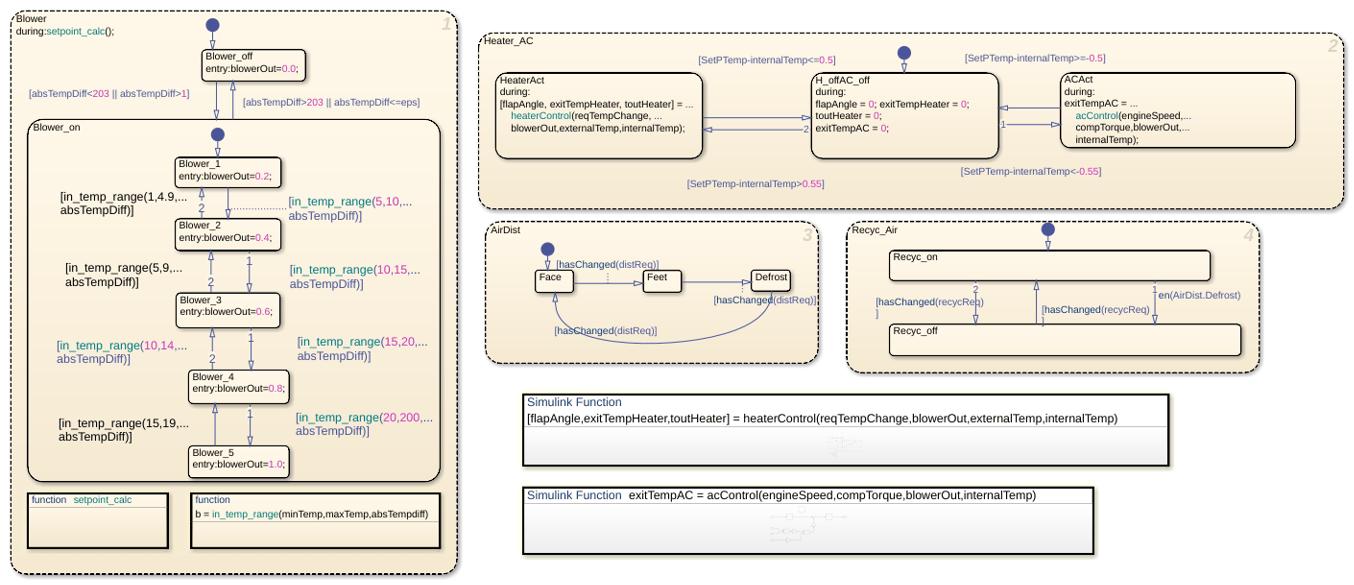
Stateflow® implements the control system. Double-click the Stateflow chart named Temperature Control to view the supervisory control logic implementation.
The Heater_AC state manages temperature control by transitioning between heating, idle, and cooling modes. Heating turns on when the setpoint exceeds the internal temperature by more than 0.55 ºC and turns off when the difference is 0.5 ºC or less. Similarly, cooling turns on when the internal temperature exceeds the setpoint by more than 0.55 ºC and turns off when the difference is 0.5 ºC or less. The controller uses a 0.05 ºC hysteresis band from 0.5 ºC to 0.55 ºC around the setpoint to prevent rapid switching between heating and cooling.
In the Blower state, the system adjusts the fan output based on the temperature difference. The system turns the blower off when the absolute temperature difference is below eps or too large. The blower runs only within the defined intermediate temperature range, allowing efficient and proportional airflow control during temperature regulation.
The two switches that trigger the Stateflow chart control the air distribution, AirDist, and recycling air, Recyc_Air. To facilitate window defrosting, the chart implements an internal transition between the two states. When the defrost state is activated, the chart turns off air recycling.
Heater and Air Conditioner Models
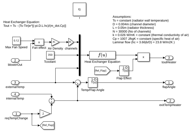
The heater model uses this equation for a heat exchanger:
Tout = Ts - (Ts-Tin)e^[(-pi*D*L*hc)/(m_dot*Cp)]
where:
Ts = constant (radiator wall temperature)
D = 0.004m (channel diameter)
L = 0.05m (radiator thickness)
N = 30000 (Number of channels)
k = 0.026 W/mK = constant (thermal conductivity of air)
Cp = 1007 J/kgK = constant (specific heat of air)
Laminar flow (hc = 3.66(k/D) = 23.8 W/m2K )
The model considers the effect of the heater flap. Similar to the blower operation, the heat flap output is proportional to the difference between the setpoint temperature and the current temperature. The greater the temperature difference, the more the heat flap opens and increases the heating effect.
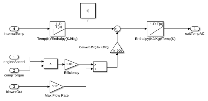
The air conditioner (AC) system is one of the two places where the climate control model interfaces with the vehicle electrical system model. The compressor loads the vehicle engine when the AC system is active. The model implements this equation to determine the AC final temperature:
y*(w*Tcomp) = m_dot*(h4-h1)
where:
y = efficiency
m_dot = mass flow rate
w = speed of the engine
Tcomp = compressor torque
h4, h1 = enthalpy
For the AC system, the model implements bang-bang control. The engine speed and compressor torque control the air temperature that exits the AC.
Heat Transfer in Cabin
These factors affect the temperature of the air the driver feels:
Temperature of the air exiting the vents
Temperature of the outside air
Number of people in the vehicle
The values of these factors are inputs into the thermodynamic model of the interior of the cabin. The model accounts for the temperature of the air exiting the vents by calculating the difference between the vent air temperature and the current temperature inside the vehicle and multiplying it by the fan speed proportion (mass flow rate). Then, each person in the vehicle adds 100 W of energy. Lastly, the model multiplies the difference between the temperature of the outside air and the interior air temperature by a lesser mass flow rate to account for the air radiating into the vehicle from the outside.
The Thermometer Display provides the output of the interior dynamics model. The output is the temperature reading of a sensor behind the head of the driver.
Electrical System
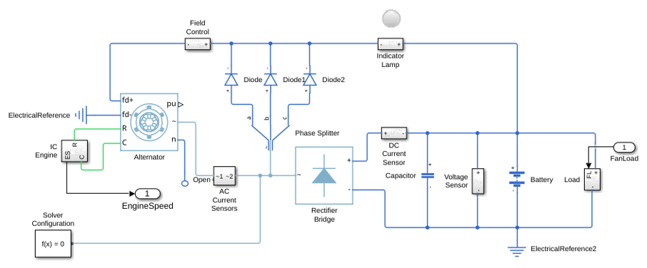
The electrical system models the vehicle at idle speed. The PID controllers ensure that the vehicle alternator is also operating at the required speed. A synchronous machine models the alternator and regulates its field current to control the output voltage. A three-phase six-pulse rectifier bridge then receives the alternator output to supply the voltage needed to charge the battery. The battery supplies the voltage for the vehicle DC bus.
The DC bus voltage is input to the climate control fan in the climate control, windscreen wipers, and the radio. As the difference between the setpoint temperature and the current vehicle temperature drops, so does the fan speed and loading on the DC bus. The feedback in the electrical system regulates the DC bus voltage.
The additional model of the vehicle electrical system allows for the changing of the engine speed. Change the engine speed to see the effect on the DC bus voltage.