Model Conditional Execution Using Triggered Subsystems
This example shows how to use subsystems to model tasks that execute based on triggers. A trigger occurs when the value and sign of a signal controlling the task execution changes. In this example, triggered subsystems log values of a sine wave signal. The logging is controlled by a square wave. The triggered subsystems log the sine wave when the sign and value of the square wave at their Trigger ports change. Then, the subsystems hold onto that sine wave value until the next trigger occurs.
Triggered Subsystem Model
In this example model, the Triggered Subsystem blocks are named after different trigger types.
Open the model.
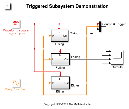
Rising - This subsystem executes when the square wave at its Trigger port changes its value in the rising direction that is when the signal changes from a negative to zero or a positive value, or from zero to a positive value. When executed, this subsystem logs the value of the input signal at that time step and holds the value until the next Rising trigger occurs.
Falling - This subsystem executes when the square wave at its Trigger port changes its value in the falling direction that is when the signal value changes from a positive to zero or a negative value, or from a positive to zero. When executed, this subsystem logs the value of the input signal at that time step and holds the value until the next Falling trigger occurs.
Either - This subsystem executes whenever the control signal changes sign or moves to zero from a positive value or from zero to a negative value, and vice-versa. In other words, this subsystem executes whenever a trigger occurs. When executed, this subsystem logs the value of the input signal at that time step and holds the value until any of the triggers occur.
Two consecutive rising or falling triggers must have more than one time step difference between them for both the triggers to be effective.
Simulation and Results
Simulate the model, and observe how the triggered subsystems respond to different triggers.
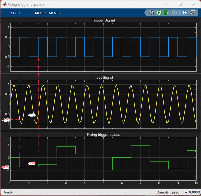
For each Scope block, the first row shows the square wave used as trigger signal. The second row shows the sine wave used as input signal. The third row shows the output to different triggers. As the square wave transitions through zero, each subsystem is triggered appropriately.
Rising trigger response - The rising trigger occurs at every 1.0 s starting from t = 0.5 s.
At t = 0.5 s, the square wave (blue signal) transitions from a negative to positive value and triggers the
Risingsubsystem. As the output signal (green signal) shows, the subsystem logs the input signal (yellow signal) value of -0.75 at t = 0.5 s, and holds onto the value until the next rising trigger occurs at t = 1.5 s.At t = 1.5 s, the output signal value is updated as the subsystem logs the input signal value of -0.55 at that time step and holds onto the value until t = 2.5 s until the next rising trigger occurs. This process repeats at every 1.0 s for every occurrence of a rising trigger.
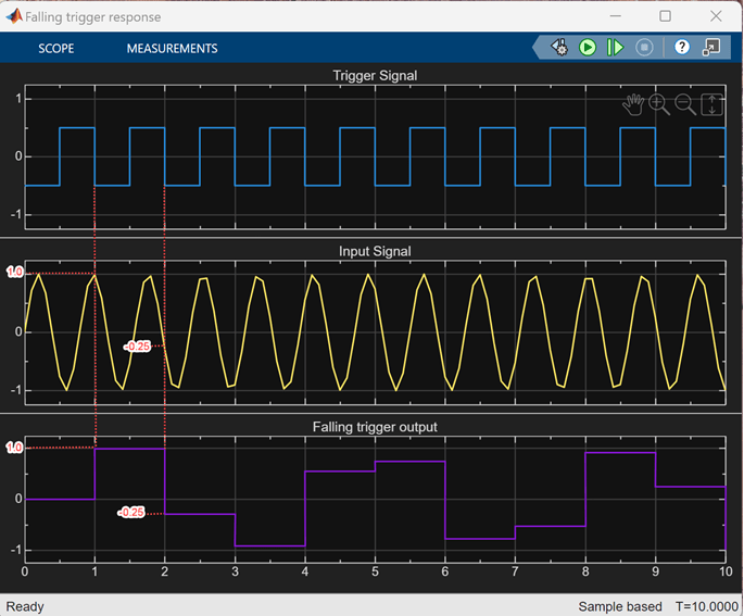
Falling trigger response - The falling trigger occurs at every 1.0 s starting from t = 1.0 s.
At t = 1.0 s, the square wave (blue signal) transitions from a positive to negative value and triggers the
Fallingsubsystem. As the output signal (violet signal) shows, the subsystem logs the input signal (yellow signal) value of 1.0 at t =1.0 s and holds onto the value until the next falling trigger t = 2.0 s.At t = 2.0 s the output signal value is updated as the subsystem logs the input signal value of -0.25 at that time step and holds onto the value until t = 3.0 s until the next falling trigger occurs. This repeats at every 1.0 s for every occurrence of a falling trigger.
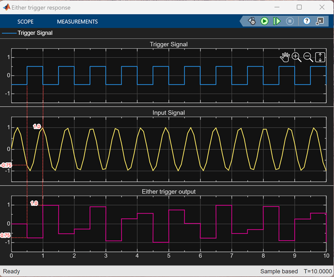
Either trigger response - The triggers occur at every 0.5 s starting at 0.5 s.
A rising trigger and a falling trigger occur at t = 0.5 s and at t = 1.0 s, respectively, and trigger the
Eithersubsystem. As the output signal (magenta signal) shows, at t = 0.5 s, the subsystem logs the input signal (yellow signal) value of -0.75 at that time step and holds onto the value until a falling trigger occurs at t =1.0 s.At t = 1.0 s, the subsystem logs the input signal value of 1.0 at that time step and holds onto the value until a rising trigger occurs until t = 1.5 s. This process repeats at every 0.5 s for every occurrence of a trigger.
See Also
Triggered Subsystem | Trigger | Signal Generator