Shape Tracing Manipulator with Simulink 3D Animation
This example shows how to configure a Simulink® model as 3D shape tracing manipulator and view its performance in a 3D environment using Simulink® 3D Animation™.
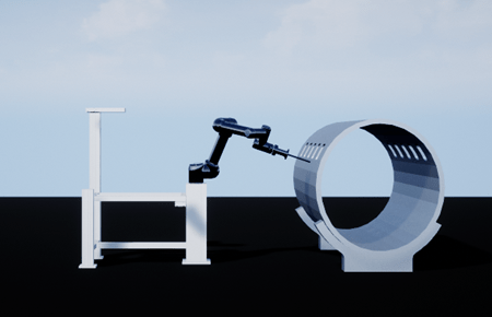
3D shape tracing enables robotic manipulators to perform tasks that require a high level of detail and consistency, such as welding complex structures, applying coatings to irregular surfaces, or conducting nondestructive testing. In this example, you import a Universal Robot (UR) manipulator and a 3D shape to trace into the 3D environment. You also import the joint configurations to publish the waypoints to the manipulator for shape tracing. Finally, view the manipulator performance in the 3D environment.
Open Model
Load the joint configuration file, load the robotMesh that initializes the rigid body tree of the robot, and open the Simulink model.
load('JointConfig.mat');
robotMesh = importrobot('ur5e_with_gripper_suction.urdf');
open_system('ShapeTracingSim3DExample.slx');
Explore Model
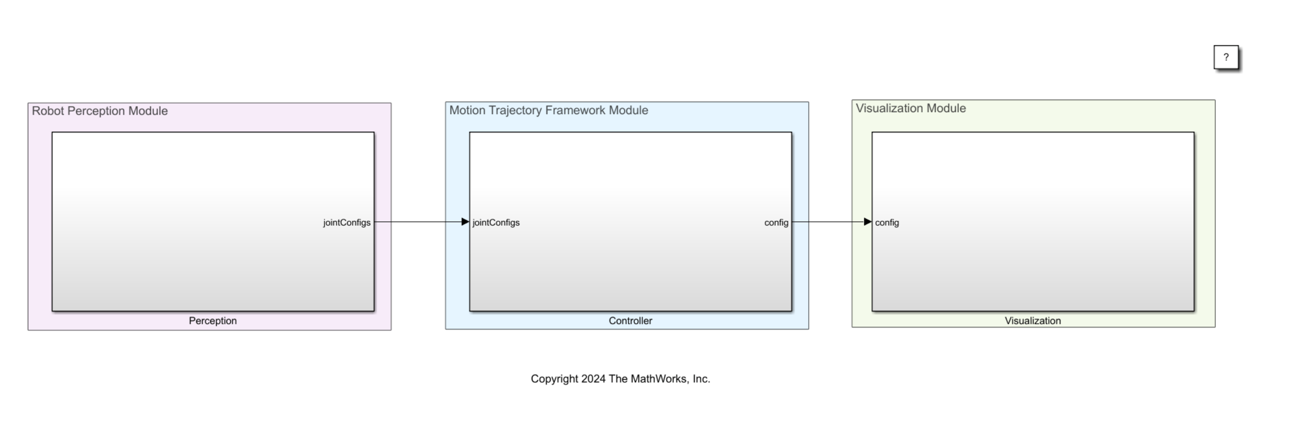
The model includes these modules to perform shape tracing efficiently by combining perception, planning, and visualization.
Robot Perception Module— Detects and interprets the objects in the 3D environmentMotion Trajectory Framework Module— Publishes waypoints for tracing the shapeVisualization Module— Displays the robot movements and the tracing process in real-time
Robot Perception Module
This module processes sensor data to understand the environment. You can use the sensors in Simulink 3D Animation to get sensor data into MATLAB®. The steps involved in perception and waypoint generation are:
The Simulation 3D Camera Get (Simulink 3D Animation) block generates the image data of the 3D environment and uses the To Video Display (Computer Vision Toolbox) block to view the image.
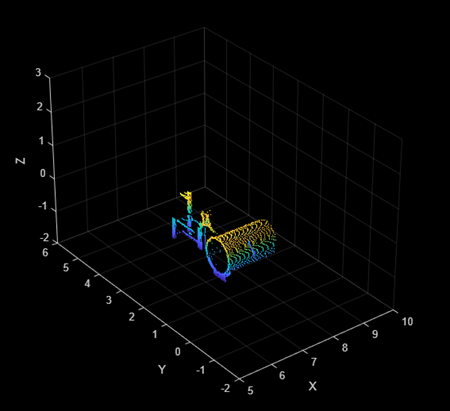
The Simulation 3D Lidar (Simulink 3D Animation) block generates the point cloud data of the 3D environment and displays the data using the Point Cloud Player.
Load the
JoitConfig.matfile to import the joint configurations.
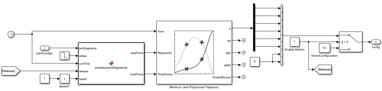
Motion Trajectory Framework Module
This module implements a joint position controller to publish the waypoints from the jointConfigs output port to the controller so that the UR manipulator traces the 3D shape. The joint segments are processed from the imported joint configuration data where you can publish waypoints corresponding to the desired 3D shape. At each time step, the controller guides the manipulator to trace a smooth, minimal-jerk trajectory along the 3D shape waypoints. After reaching the last waypoint, the controller reverses direction along the 3D shape back to the first waypoint.
The controller also provides two dynamic re-configurable parameters.
Release— A Boolean parameter that you can enable to release the robot from the current positionSpeed— A slider gain parameter that you can use to increase or decrease the speed of robot motion
Visualization Module
This module uses the Simulation 3D Scene Configuration (Simulink 3D Animation) block to create and display the 3D environment in the Simulation 3D Viewer window. The Simulation 3D Actor (Simulink 3D Animation) block loads the robotComponents.mat file to import the robotic arm and other components in the 3D environment. The Simulation 3D Robot (Robotics System Toolbox) uses the generated waypoints to control the robot movement and trace the 3D shape.
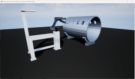
Simulate Model
Simulate the model and visualize the manipulator tracing the 3D shape in the Simulation 3D Viewer window.
The point cloud player displays the point cloud data.
The Simulation 3D Camera block outputs a 3D camera image of the simulation.
See Also
Topics
- Interact with Unreal Engine Simulation Environment (Simulink 3D Animation)
- Generate Automated ros_control Plugin for 3-D Shape Tracing Manipulator (Robotics System Toolbox)