PWM
Generate ideal pulse width modulated signal corresponding to input duty cycle

Libraries:
Simulink /
Discontinuities
Description
Use the PWM block to generate an ideal pulse width modulated signal.
Pulse-width modulation (PWM) is a technique for encoding an analog signal using square pulses. This encoding is achieved by controlling the fraction of one period of the square wave that is set to high. This fraction is the duty cycle of the signal. The relationship between the modulated signal and the input duty cycle can be simply described as:
where ymax and ymin are the upper and lower bounds of the output signal, respectively. For
the PWM block, the duty cycle is constrained to [0,1].
The ideal PWM signal is proportional to the duty cycle D.
Examples
This example shows you how to control a boost converter using the PWM block in Simulink®. the boost converter in this model uses the Boost Converter (Simscape Electrical) block from the Simscape™ Electrical™ library.
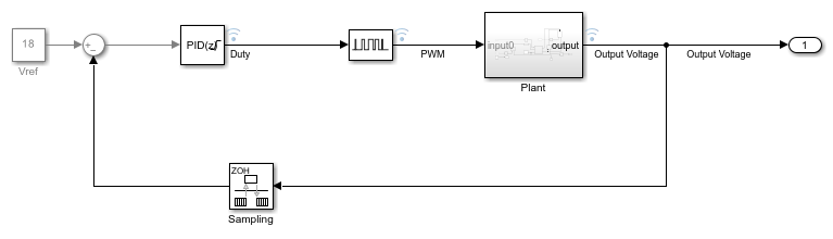
A PWM signal is used to control the switching device, or gate, of the boost converter. The PID controller generates the command signal, or the duty cycle, to track the desired step-up voltage (Vref) of 18V
This is a relatively high frequency application; the switching gate operates at around 200kHz. Therefore, a pulse period of 1/200,000 or 5e-6s is chosen for the PWM signal.
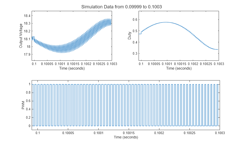
Given the small time steps, the boostconverter_pwm model provided with the example is loaded from a steady state at 0.069s.

A visualization of the boost converter operation around the 0.1s mark is shown below.
For alternate physical modeling implementations of PWM control, see Pulse Width Modulation (Simscape Electrical).
Ports
Input
Output
Parameters
Block Characteristics
Data Types |
|
Direct Feedthrough |
|
Multidimensional Signals |
|
Variable-Size Signals |
|
Zero-Crossing Detection |
|
Algorithms

For a pulse starting at time tk
where pw is the pulse width. For a given period P, pw is proportional to the duty cycle D
In Discrete sampling mode, the input duty cycle signal is sampled at the rate specified by the Run at fixed time intervals parameter.
For a specified sampling rate tS , the number of samples needed for a pulse of width pw can be expressed as follows
where nP is the number of samples needed to simulate a pulse of period P.
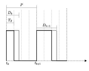
Consider a nominal pulse of period P with the sampling rate of the block set to be tS= 0.25 P. The number of samples needed for one period of the pulse, nP= 4. Thus, for the input duty cycle D= 0.47 , the number of samples n pw is floored to = 1. Therefore, the pulse is high for 1 of the 4 samples in the period.
Extended Capabilities
Version History
Introduced in R2020b