Component Interface View
R2026bDisplay component interfaces to trace port connections and author ports
Renamed from Interface Display in R2024b
Description
The Component Interface View displays the input ports, output ports, and boundary of the current subsystem or model.
When you build large model hierarchies, the Component Interface View can help you:
Identify input and output ports.
Trace input ports to their destinations.
Trace output ports to their sources.
Author input and output ports.
Edit types assigned to ports.
The Component Interface View also supports the same interactions as the Simulink® Editor. For example, you can edit block diagrams and display information overlays such as sample time.

Open the Component Interface View
Simulink Toolstrip: On the Modeling tab, in the Design gallery, click Interface View.
Simulink Editor: Press Ctrl+Shift+V.
MATLAB® Command Window: Open a model or subsystem. Then, enter
interfaceView.
Examples
The Component Interface View helps you identify the ports of a model or subsystem, regardless of where the corresponding blocks are in the block diagram.
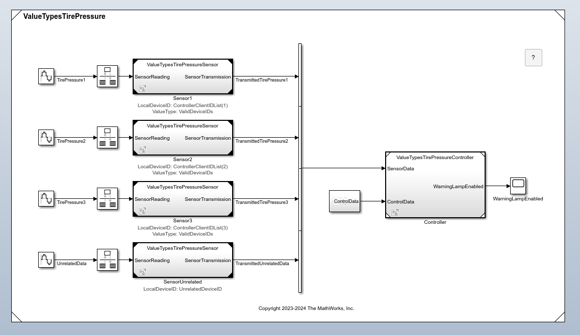
For example, consider the ValueTypesTirePressure model hierarchy.
openExample("simulink/ValueTypesAtInterfacesExample")The Component Interface View can help you quickly identify that the top level of the model hierarchy does not contain any input or output ports. On the Modeling tab, in the Design gallery, click Interface View. Alternatively, press Ctrl+Shift+V.
When you navigate into a model that has input and output ports, such as
ValueTypesTirePressureSensor, the Component Interface
View displays the input and output ports on the component boundary.
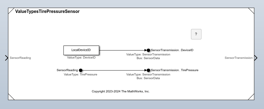
Where the Component Interface View displays the ports depends on the type of component.
Models — By default, the Component Interface View displays the input ports on the left and the output ports on the right. To move a port in the Component Interface View, select the port and use the arrow keys. To save the modified Component Interface View port locations, save the model.
Subsystems — The Component Interface View displays each port in the same location as the subsystem block displays the port. When you move a port in the Component Interface View, you also move the port on the subsystem block.
To find the blocks that correspond with a port, click the corresponding port icon on the component boundary. The Component Interface View selects the corresponding blocks and draws lines between the port and the blocks.
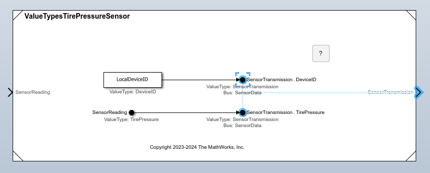
The Component Interface View lets you trace the usage of a bus, signal, or message associated with an input or output port.
For example, consider the ValueTypesTirePressureController model
in the ValueTypesTirePressure model hierarchy.
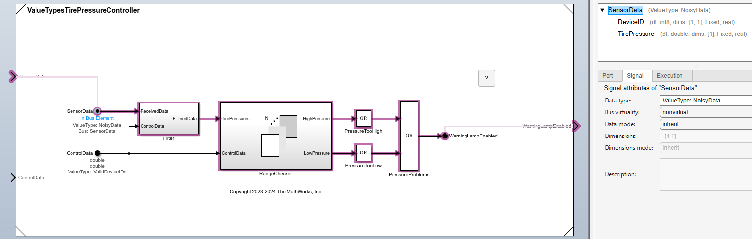
openExample("simulink/ValueTypesAtInterfacesExample")The Component Interface View shows two input ports and an output port on the boundary of the model. On the Modeling tab, in the Design gallery, click Interface View. Alternatively, press Ctrl+Shift+V.
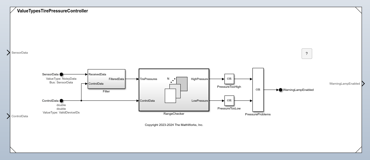
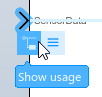
To trace the usage of the bus, signal, or message associated with a port, select the port. Then, click Show usage.
The Property Inspector opens. The direction of the trace depends on the type of port.
Input port — The trace goes to the destination.
Output port — The trace goes to the source.
In this example, the Component Interface View traces the usage of a bus from the selected input port to an output port.
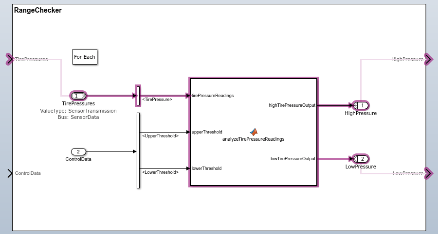
The Component Interface View traces usage through subsystem boundaries.
For example, the bus usage traces through the RangeChecker
subsystem.
To trace the usage of a different element associated with the port, in the Property Inspector, select the element.
The Component Interface View helps you add, remove, and modify ports at a model or subsystem interface.
For example, consider a new model.
To author the model interface, open the Component Interface View. On the Modeling tab, in the Design gallery, click Interface View. Alternatively, press Ctrl+Shift+V.
To view port authoring options, click the component boundary.

While input ports are typically on the left and output ports are typically on the right, you can create the ports on any side.
To create an input port, select Input.
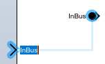
The Component Interface View adds a port and a block that represents
the port. Optionally, enter a new name for the port. For example, enter
In.
To create an output port, select Output.
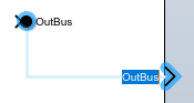
The Component Interface View adds a port and a block that represents
the port. Optionally, enter a new name for the port. For example, enter
Out.
Optionally, add blocks to the block diagram. For example, add a Gain block.
To connect a port, perform one of these actions:
Drag a port on a block that represents a component port to a supported block port.

Drag a port on the component boundary to a supported block port.
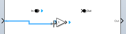
Drag a block port to a supported port on the component boundary.
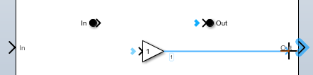
Drag a port on the component boundary to a supported port on the component boundary.

Drag a block port or component port to a location on the component boundary. The Component Interface View creates the supported type of component port. For example, when you drag an input port to the component boundary, the Component Interface View creates an output port.

To delete a port, select the port. Then, press Delete.
You can use the Component Interface View in combination with the Type Editor to create, modify, and apply types to ports at a component interface.
For example, open the ComponentBasedModeling project. The project opens the top model in a model hierarchy. To update the line styles, in the Simulink Toolstrip, on the Modeling tab, click Update Model or Run. Updating the line styles can help you visually identify buses.
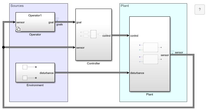
To inspect the interfaces of the model components, open the Component Interface View. On the Modeling tab, in the Design gallery, click Interface View. Alternatively, press Ctrl+Shift+V.
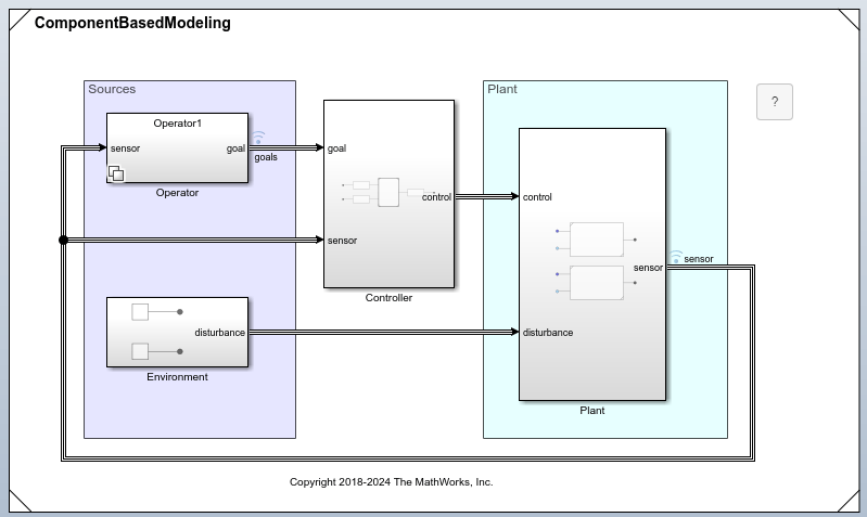
Suppose you want to define the interface of the Plant subsystem with Simulink.Bus objects.
Open the Plant subsystem.
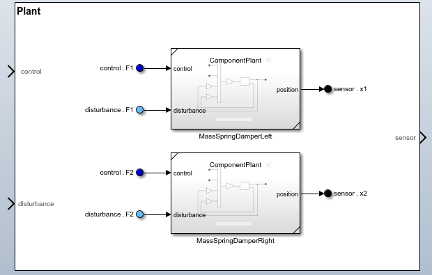
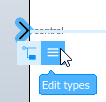
To begin editing port data types, select a port. For example, select the new control port. Then, click Edit types.
The docked Type Editor opens. Expand the ComponentControllerData dictionary, which contains Simulink.Bus objects named Controls, Goals, and Sensors.
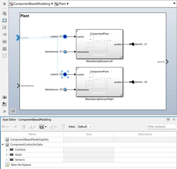
Right-click the Controls bus object. Then, click Apply type to selected blocks and ports.
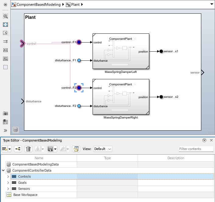
The port now uses the Controls bus object.
Optionally, create a bus object to represent the port named disturbance. The Sensors bus object can represent the port named sensor.
To apply bus objects to the remaining ports, in the Component Interface View, select a port. Then, in the Type Editor, right-click the corresponding bus object and click Apply type to selected blocks and ports.

