Lever
Generic mechanical lever
Libraries:
Simscape /
Foundation Library /
Mechanical /
Mechanisms
Description
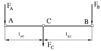
The Lever block represents a mechanical lever in its generic form, known as a free or summing lever, shown in the following schematic.

The summing lever equations are derived with the assumption of small angle deviation from initial position:
where
vA, vB, vC are level joint velocities.
FA, FB, FC are level joint forces.
lAC, lBC are arm lengths.
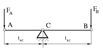
The above equations are derived with the assumption that the lever sums forces and motions at node C. The assumption is arbitrary and does not impose any limitations on how the forces or motions are applied to the lever. In other words, any of the lever nodes can be “input” or “output” nodes, depending on the value of the force. Moreover, any of the block nodes can be connected to the reference point, thus converting a three-node lever into a first-class lever, with the fulcrum in the middle, or a second-class lever, with the fulcrum at the end.
The following illustration shows a schematic of a first-class lever, with the fulcrum in the middle.

It is described with the following equations:
The next illustration shows a schematic of a second-class lever, with the fulcrum at node A.

It is described with the following equations:
The Linkage Mechanism example illustrates the use of the Lever block in three different modes. Linkages L_1 and L_4 simulate first-class levers with the fulcrum at the end. Linkage L_2 represents a summing lever. Linkage L_3 simulates a second-class lever with the fulcrum in the middle.
As far as the block directionality is concerned, the joints' absolute displacements are positive if they are in line with the globally assigned positive direction.
Variables
To set the priority and initial target values for the block variables prior to simulation, use the Initial Targets section in the block dialog box or Property Inspector. For more information, see Set Priority and Initial Target for Block Variables.
Nominal values provide a way to specify the expected magnitude of a variable in a model. Using system scaling based on nominal values increases the simulation robustness. Nominal values can come from different sources, one of which is the Nominal Values section in the block dialog box or Property Inspector. For more information, see Modify Nominal Values for a Block Variable.
Examples
Ports
Conserving
Parameters
Extended Capabilities
Version History
Introduced in R2007a

