Constant Volume Chamber (MA)
Chamber with fixed volume of moist air and variable number of ports
Libraries:
Simscape /
Foundation Library /
Moist Air /
Elements
Description
The Constant Volume Chamber (MA) block models mass and energy storage in a moist air network. The chamber contains a constant volume of moist air. It can have between one and four inlets. The enclosure can exchange mass and energy with the connected moist air network and exchange heat with the environment, allowing its internal pressure and temperature to evolve over time. The pressure and temperature evolve based on the compressibility and thermal capacity of the moist air volume. Liquid water condenses out of the moist air volume when it reaches saturation.
The block equations use these symbols. Subscripts a
,
w
, g
, and d
indicate the
properties of dry air, water vapor, trace gas, and water droplets, respectively.
Subscript ws
indicates water vapor at saturation. Subscripts
A
, H
, and S
indicate the
appropriate port. Subscript I
indicates the properties of the
internal moist air volume.
Mass flow rate | |
Φ | Energy flow rate |
Q | Heat flow rate |
p | Pressure |
ρ | Density |
R | Specific gas constant |
V | Volume of moist air inside the chamber |
cp | Specific heat at constant volume |
h | Specific enthalpy |
u | Specific internal energy |
x | Mass fraction (xw is specific humidity, which is another term for water vapor mass fraction) |
y | Mole fraction |
φ | Relative humidity |
r | Humidity ratio |
rd | Mass ratio of water droplets to moist air |
T | Temperature |
t | Time |
The net flow rates into the moist air volume inside the chamber are
where:
condense is the rate of condensation.
d,evap is the rate of water droplet evaporation.
Φcondense is the rate of energy loss from the condensed water.
λd is the value of the Fraction of condensate entrained as water droplets parameter.
ΦS is the rate of energy added by the sources of moisture and trace gas. and are mass flow rates of water and gas, respectively, through port S. The values of , , and ΦS are determined by the moisture and trace gas sources connected to port S of the chamber, or by the corresponding parameter values.
If a port is not visible, then the terms with the subscript corresponding to the port name are 0.
Water vapor mass conservation relates the water vapor mass flow rate to the dynamics of the humidity in the internal moist air volume:
Similarly, trace gas mass conservation relates the trace gas mass flow rate to the dynamics of the trace gas level in the internal moist air volume:
The water droplets mass conservation equation relates the water droplet mass flow rate to the entrained water droplet dynamics in the internal moist air volume
Mixture mass conservation relates the mixture mass flow rate to the dynamics of the pressure, temperature, and mass fractions of the internal moist air volume:
Finally, energy conservation relates the energy flow rate to the dynamics of the pressure, temperature, and mass fractions of the internal moist air volume:
The equation of state relates the mixture density to the pressure and temperature:
The mixture specific gas constant is
Flow resistance and thermal resistance are not modeled in the chamber:
When the moist air volume reaches saturation, condensation may occur. The specific humidity at saturation is
where:
φws is the relative humidity at saturation (typically 1).
pwsI is the water vapor saturation pressure evaluated at TI.
The rate of condensation is
where τcondense is the value of the Water vapor condensation time constant parameter.
The rate of evaporation is
where τevap is the value of the Water droplets evaporation time constant parameter.
Assumptions and Limitations
The chamber walls are perfectly rigid.
Flow resistance between the chamber inlet and the moist air volume is not modeled. Connect a Local Restriction (MA) block or a Flow Resistance (MA) block to port A to model the pressure losses associated with the inlet.
Thermal resistance between port H and the moist air volume is not modeled. Use Thermal library blocks to model thermal resistances between the moist air mixture and the environment, including any thermal effects of a chamber wall.
Examples
Vehicle HVAC System
Models moist air flow in a vehicle heating, ventilation, and air conditioning (HVAC) system. The vehicle cabin is represented as a volume of moist air exchanging heat with the external environment. The moist air flows through a recirculation flap, a blower, an evaporator, a blend door, and a heater before returning to the cabin. The recirculation flap selects flow intake from the cabin or from the external environment. The blender door diverts flow around the heater to control the temperature.
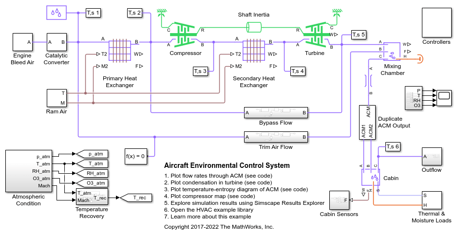
Aircraft Environmental Control System
Models an aircraft environmental control system (ECS) that regulates pressure, temperature, humidity, and ozone (O3) to maintain a comfortable and safe cabin environment. Cooling and dehumidification are provided by the air cycle machine (ACM), which operates as an inverse Brayton cycle to remove heat from pressurized hot engine bleed air. Some hot bleed air is mixed directly with the output of the ACM to adjust the temperature. Pressurization is maintained by the outflow valve in the cabin. This model simulates the ECS operating from a hot ground condition to a cold cruise condition and back to a cold ground condition.
Medical Ventilator with Lung Model
Models a positive-pressure medical ventilator system. A preset flow rate is supplied to the patient. The lungs are modeled with the Translational Mechanical Converter (MA), which converts moist air pressure into translational motion. By setting the Interface cross-sectional area to unity, displacement in the mechanical translational network becomes a proxy for volume, force becomes a proxy for pressure, spring constant becomes a proxy for respiratory elastance, and damping coefficient becomes a proxy for respiratory resistance.
Ports
Output
W — Rate of condensation leaving system, kg/s
physical signal
Physical signal output port that measures the rate of condensation that leaves the system. This value does not include the portion of condensation that is entrained as water droplets.
F — Vector physical signal containing pressure, temperature, humidity, and trace gas levels data
physical signal vector
Physical signal output port that outputs a vector signal. The vector contains the pressure (in Pa), temperature (in K), moisture level, and trace gas level measurements inside the component. Use the Measurement Selector (MA) block to unpack this vector signal.
Conserving
A — Chamber inlet
moist air
Moist air conserving port associated with the chamber inlet.
B — Chamber inlet
moist air
Moist air conserving port associated with the second chamber inlet.
Dependencies
This port is visible if you set the Number of
ports parameter to 2
,
3
, or
4
.
C — Chamber inlet
moist air
Moist air conserving port associated with the third chamber inlet.
Dependencies
This port is visible if you set the Number of
ports parameter to 3
or
4
.
D — Chamber inlet
moist air
Moist air conserving port associated with the fourth chamber inlet. If a chamber has four inlet ports, you can use it as a junction in a cross connection.
Dependencies
This port is visible only if you set the Number of
ports parameter to
4
.
H — Temperature inside chamber
thermal
Thermal conserving port associated with the temperature of the air mixture inside the chamber.
S — Inject or extract moisture and trace gas
moist air source
Connect this port to port S of a block from the Moisture & Trace Gas Sources library to add or remove moisture and trace gas. For more information, see Using Moisture and Trace Gas Sources.
Dependencies
This port is visible only if you set the Moisture and
trace gas source parameter to
Controlled
.
Parameters
Main
Chamber volume — Volume of moist air in the chamber
0.001 m^3
(default)
Volume of moist air in the chamber. The chamber is rigid and therefore its volume is constant during simulation. The chamber is assumed to be completely filled with moist air at all times.
Number of ports — Number of inlet ports in the chamber
1
(default) | 2
| 3
| 4
Number of inlet ports in the chamber. The chamber can have between one and four ports, labeled from A to D. When you modify the parameter value, the corresponding ports are exposed or hidden in the block icon.
Cross-sectional area at port A — Area normal to flow path at the chamber inlet
0.01 m^2
(default)
Cross-sectional area of the chamber inlet at port A, in the direction normal to air flow path.
Cross-sectional area at port B — Area normal to flow path at the chamber inlet
0.01 m^2
(default)
Cross-sectional area of the chamber inlet at port B, in the direction normal to air flow path.
Dependencies
Enabled when port B is visible, that is, when
the Number of ports parameter is set to
2
, 3
, or
4
.
Cross-sectional area at port C — Area normal to flow path at the chamber inlet
0.01 m^2
(default)
Cross-sectional area of the chamber inlet at port C, in the direction normal to air flow path.
Dependencies
Enabled when port C is visible, that is, when
the Number of ports parameter is set to
3
or
4
.
Cross-sectional area at port D — Area normal to flow path at the chamber inlet
0.01 m^2
(default)
Cross-sectional area of the chamber inlet at port D, in the direction normal to air flow path.
Dependencies
Enabled when port D is visible, that is, when
the Number of ports parameter is set to
4
.
Moisture and Trace Gas
Relative humidity at saturation — Relative humidity above which condensation occurs
1
(default)
Relative humidity above which condensation occurs.
Water vapor condensation time constant — Time scale for condensation
1e-3 s
(default) | positive scalar
Characteristic time scale at which an oversaturated moist air volume returns to saturation by condensing out excess moisture.
Water droplets evaporation time constant — Time scale for evaporation
1e-3 s
(default) | positive scalar
Characteristic time scale at which water droplets evaporate to vapor.
Fraction of condensate entrained as water droplets — Fraction of condensate in water droplets
1
(default) | scalar in the range [0,1]
Fraction of the condensate in the moist air that is entrained as water droplets.
Moisture and trace gas source — Model moisture and trace gas levels
None
(default) | Constant
| Controlled
This parameter controls visibility of port S and provides these options for modeling moisture and trace gas levels inside the component:
None
— No moisture or trace gas is injected into or extracted from the block. Port S is hidden. This is the default.Constant
— Moisture and trace gas are injected into or extracted from the block at a constant rate. The same parameters as in the Moisture Source (MA) and Trace Gas Source (MA) blocks become available in the Moisture and Trace Gas section of the block interface. Port S is hidden.Controlled
— Moisture and trace gas are injected into or extracted from the block at a time-varying rate. Port S is exposed. Connect the Controlled Moisture Source (MA) and Controlled Trace Gas Source (MA) blocks to this port.
Moisture added or removed — Select whether the block adds or removes moisture as water vapor or water droplets
Water vapor
(default) | Water droplets
Select whether the block adds or removes moisture as water vapor or water droplets.
Dependencies
To enable this parameter, set Moisture and trace gas
source to Constant
.
Water vapor evaporated from liquid or condensed to liquid — How the block adds or removes water vapor
off
(default) | on
Select how the block adds or removes water vapor. If you clear this check box, the enthalpy of the added or removed moisture corresponds to the enthalpy of water vapor, which is greater than that of liquid water.
If you select this check box, the enthalpy of the added or removed moisture corresponds to the enthalpy of liquid water, which is less than that of water vapor. When water vapor is added, it evaporates from liquid and the latent heat is contributed by the connected fluid volume. When water vapor is removed, it condenses to liquid and the latent heat is released to the connected fluid volume.
Dependencies
To enable this parameter, set Moisture and trace gas
source to Constant
and
Moisture added or removed to
Water vapor
.
Rate of moisture added — Constant mass flow rate through the block
0 kg/s
(default)
Water vapor or water droplets mass flow rate through the block. A positive value adds moisture to the connected moist air volume. A negative value extracts moisture from that volume.
Dependencies
To enable this parameter, set Moisture and trace gas
source to Constant
.
Added moisture temperature specification — Select specification method for the temperature of added moisture
Atmospheric
temperature
(default) | Specified temperature
Select a specification method for the moisture temperature:
Atmospheric temperature
— Use the atmospheric temperature, specified by the Moist Air Properties (MA) block connected to the circuit.Specified temperature
— Specify a value by using the Temperature of added moisture parameter.
Dependencies
To enable this parameter, set Moisture and trace gas
source to Constant
.
Temperature of added moisture — Moisture temperature
293.15 K
(default)
Enter the desired temperature of added moisture. This temperature remains constant during simulation. The block uses this value to evaluate the specific enthalpy of the added moisture only. The specific enthalpy of removed moisture is based on the temperature of the connected moist air volume.
Dependencies
To enable this parameter, set Moisture and trace gas
source to Constant
and
Added moisture temperature specification to
Specified temperature
.
Rate of trace gas added — Constant mass flow rate through the block
0 kg/s
(default)
Trace gas mass flow rate through the block. A positive value adds trace gas to the connected moist air volume. A negative value extracts trace gas from that volume.
Dependencies
To enable this parameter, set Moisture and trace gas
source to Constant
.
Added trace gas temperature specification — Select specification method for the temperature of added trace gas
Atmospheric
temperature
(default) | Specified temperature
Select a specification method for the trace gas temperature:
Atmospheric temperature
— Use the atmospheric temperature, specified by the Moist Air Properties (MA) block connected to the circuit.Specified temperature
— Specify a value by using the Temperature of added trace gas parameter.
Dependencies
To enable this parameter, set Moisture and trace gas
source to Constant
.
Temperature of added trace gas — Trace gas temperature
293.15 K
(default)
Enter the desired temperature of added trace gas. This temperature remains constant during simulation. The block uses this value to evaluate the specific enthalpy of the added trace gas only. The specific enthalpy of removed trace gas is based on the temperature of the connected moist air volume.
Dependencies
To enable this parameter, set Moisture and trace gas
source to Constant
and
Added trace gas temperature specification
to Specified temperature
.
Initial Conditions
Initial pressure — Moist air pressure at the start of simulation
0.101325 MPa
(default) | positive scalar
Moist air pressure at the start of the simulation.
Initial pressure priority — Pressure parameter priority
High
(default) | Low
| None
Priority the solver assigns to the Initial pressure parameter when initializing the block.
Set this parameter to High
to define your
initial conditions. You may need to set this parameter to
Low
or None
if
this initial condition conflicts with the initial conditions of another
block.
Initial temperature — Temperature at the start of simulation
293.15 K
(default) | positive scalar
Initial moist air temperature.
Initial temperature priority — Temperature parameter priority
High
(default) | Low
| None
Priority the solver assigns to the Initial temperature parameter when initializing the block.
Set this parameter to High
to define your
initial conditions. You may need to set this parameter to
Low
or None
if
this initial condition conflicts with the initial conditions of another
block.
Initial humidity specification — Humidity specification
Relative humidity
(default) | Specific humidity
| Mole fraction
| Humidity ratio
| Wet-bulb temperature
Method to specify the initial moist air humidity.
Initial relative humidity — Relative humidity at the start of simulation
0.5
(default) | scalar in the range of [0,1]
Relative humidity in the moist air at the start of the simulation. The relative humidity is the ratio of the water vapor partial pressure to the water vapor saturation pressure, or the ratio of the water vapor mole fraction to the water vapor mole fraction at saturation.
Dependencies
To enable this parameter, set Initial humidity
specification to Relative
humidity
.
Initial relative humidity priority — Relative humidity parameter priority
High
(default) | Low
| None
Priority the solver assigns to the Initial relative humidity parameter when initializing the block.
Set this parameter to High
to define your
initial conditions. You may need to set this parameter to
Low
or None
if
this initial condition conflicts with the initial conditions of another
block.
Dependencies
To enable this parameter, set Initial humidity
specification to Relative
humidity
.
Initial specific humidity — Specific humidity at the start of simulation
0.01
(default) | scalar in the range of [0,1]
Specific humidity in the moist air at the start of simulation. The specific humidity is the mass fraction of water vapor to the combined total mass of water vapor, trace gas, and dry air.
Dependencies
To enable this parameter, set Initial humidity
specification to Specific
humidity
.
Initial specific humidity priority — Specific humidity parameter priority
High
(default) | Low
| None
Priority the solver assigns to the Initial specific humidity parameter when initializing the block.
Set this parameter to High
to define your
initial conditions. You may need to set this parameter to
Low
or None
if
this initial condition conflicts with the initial conditions of another
block.
Dependencies
To enable this parameter, set Initial humidity
specification to Specific
humidity
.
Initial water vapor mole fraction — Mole fraction of water vapor at the start of simulation
0.01
(default) | scalar in the range [0,1]
Mole fraction of the water vapor in the moist air channel at the start of simulation. The water vapor mole fraction is relative to the combined molar quantity of water vapor, trace species, and dry air.
Dependencies
To enable this parameter, set Initial humidity
specification to Mole
fraction
.
Initial water vapor mole fraction priority — Water vapor mole fraction humidity parameter priority
High
(default) | Low
| None
Priority the solver assigns to the Initial water vapor mole fraction parameter when initializing the block.
Set this parameter to High
to define your
initial conditions. You may need to set this parameter to
Low
or None
if
this initial condition conflicts with the initial conditions of another
block.
Dependencies
To enable this parameter, set Initial humidity
specification to Mole
fraction
.
Initial humidity ratio — Humidity ratio at the start of simulation
0.01
(default) | scalar in the range [0,1]
Humidity ratio in the moist air channel at the start of the simulation. The humidity ratio is the ratio of the mass of water vapor to the mass of dry air and trace gas.
Dependencies
To enable this parameter, set Initial humidity
specification to Humidity
ratio
.
Initial humidity ratio priority — Humidity ratio parameter priority
High
(default) | Low
| None
Priority the solver assigns to the Initial humidity ratio humidity parameter when initializing the block.
Set this parameter to High
to define your
initial conditions. You may need to set this parameter to
Low
or None
if
this initial condition conflicts with the initial conditions of another
block.
Dependencies
To enable this parameter, set Initial humidity
specification to Humidity
ratio
.
Initial wet-bulb temperature — Wet-bulb temperature at the start of simulation
287 K
(default) | scalar in the range [0,1]
Wet-bulb temperature at the start of the simulation. The block uses this value to calculate humidity.
Dependencies
To enable this parameter, set Initial humidity
specification to Wet-bulb
temperature
.
Initial wet-bulb temperature priority — Wet-bulb temperature parameter priority
High
(default) | Low
| None
Priority the solver assigns to the Initial wet-bulb temperature parameter when initializing the block.
Set this parameter to High
to define your
initial conditions. You may need to set this parameter to
Low
or None
if
this initial condition conflicts with the initial conditions of another
block.
Dependencies
To enable this parameter, set Initial humidity
specification to Wet-bulb
temperature
.
Initial trace gas specification — Measurement type of trace gas
Mass fraction
(default) | Mole fraction
Measurement type of trace gas.
Initial trace gas mass fraction — Amount of trace gas in the moist air channel
0.001
(default) | scalar in the range [0,1]
Amount of trace gas in the moist air by mass fraction at the start of the simulation. The mass fraction is relative to the combined total mass of water vapor, trace gas, and dry air.
The block ignores this parameter if the Trace gas
model parameter in the Moist Air Properties (MA) block is
None
.
Dependencies
To enable this parameter, set Initial trace gas
specification to Mass
fraction
.
Initial trace gas mass fraction priority — Trace gas mass fraction parameter priority
High
(default) | Low
| None
Priority the solver assigns to the Initial trace gas mass fraction priority parameter when initializing the block.
Set this parameter to High
to define your
initial conditions. You may need to set this parameter to
Low
or None
if
this initial condition conflicts with the initial conditions of another
block.
Dependencies
To enable this parameter, set Initial trace gas
specification to Mass
fraction
.
Initial trace gas mole fraction — Mole fraction of trace gas at the start of simulation
0.001
(default) | scalar in the range [0,1]
Amount of trace gas in the moist air channel by mole fraction at the start of the simulation. The mole fraction is relative to the combined molar total of water vapor, trace gas, and dry air.
The block ignores this parameter if the Trace gas
model parameter in the Moist Air Properties (MA) block is
None
.
Dependencies
To enable this parameter, set Initial trace gas
specification to Mole
fraction
.
Initial trace gas mole fraction priority — Trace gas mole fraction parameter priority
High
(default) | Low
| None
Priority the solver assigns to the Initial trace gas mole fraction priority parameter when initializing the block.
Set this parameter to High
to define your
initial conditions. You may need to set this parameter to
Low
or None
if
this initial condition conflicts with the initial conditions of another
block.
Dependencies
To enable this parameter, set Initial trace gas
specification to Mole
fraction
.
Initial mass ratio of water droplets to moist air — Ratio of water droplets to moist air
0
(default) | positive scalar
Initial mass ratio of water droplets to moist air.
Initial mass ratio of water droplets to moist air priority — Mass ratio of water droplets to moist air parameter priority
High
(default) | Low
| None
Priority the solver assigns to the Initial mass ratio of water droplets to moist air priority parameter when initializing the block.
Set this parameter to High
to define your
initial conditions. You may need to set this parameter to
Low
or None
if
this initial condition conflicts with the initial conditions of another
block.
Extended Capabilities
C/C++ Code Generation
Generate C and C++ code using Simulink® Coder™.
Version History
Introduced in R2018aR2024b: Updated options for initial conditions
You can now specify initial conditions for the block as parameters.
R2024b: Model water droplets suspended in moist air flow
Blocks in the moist air domain can now model water droplets suspended in a moist air flow. To model water droplets, select Enable entrained water droplets in the Moist Air Properties (MA) block connected to your moist air network.
MATLAB Command
You clicked a link that corresponds to this MATLAB command:
Run the command by entering it in the MATLAB Command Window. Web browsers do not support MATLAB commands.
Select a Web Site
Choose a web site to get translated content where available and see local events and offers. Based on your location, we recommend that you select: .
You can also select a web site from the following list
How to Get Best Site Performance
Select the China site (in Chinese or English) for best site performance. Other MathWorks country sites are not optimized for visits from your location.
Americas
- América Latina (Español)
- Canada (English)
- United States (English)
Europe
- Belgium (English)
- Denmark (English)
- Deutschland (Deutsch)
- España (Español)
- Finland (English)
- France (Français)
- Ireland (English)
- Italia (Italiano)
- Luxembourg (English)
- Netherlands (English)
- Norway (English)
- Österreich (Deutsch)
- Portugal (English)
- Sweden (English)
- Switzerland
- United Kingdom (English)
Asia Pacific
- Australia (English)
- India (English)
- New Zealand (English)
- 中国
- 日本Japanese (日本語)
- 한국Korean (한국어)