Main Content

Sinusoid

Model DC offset and sinusoidal modulation

  • Sinusoid block

Libraries:
RF Blockset / Circuit Envelope / Sources

Description

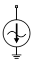
The Sinusoid block implements a voltage or current source that provides a DC offset and sine wave modulation. This block can be used with each listed block carrier in the circuit envelope environment.

The block implements the following voltage (or current) relationships for the in-phase (ui), and quadrature (uq), components of the kth listed block carrier:

uk,i(t)=Di+Aisin(wk(tτ))uk,q(t)=Dq+Aqsin(wk(tτ))

where:

  • Di and Dq are DC offsets.

  • Ai and Aq are in-phase and quadrature amplitudes.

  • τ is the time delay.

  • ωk is the specified modulation frequency at a given carrier frequency fk.

  • t is the time.

Note

Sinusoid block does not support frame-based processing (supported by the Configuration blocks) as it uses SL Sine wave block. This block errors if the Samples per frame is more than 1 in the configuration block.

Sinusoid block mask icons are dynamic and show the current type of source. This table shows you how the icons on this block vary based on the type of source you set on the Source type parameter on the block.

Source type: Ideal voltageSource type: Ideal current

Sinusoid block icon with Source type is set to Ideal voltage.

Sinusoid block icon with Source type is set to Ideal current.

Parameters

expand all

Wave type, specified as:

  • Ideal Voltage — The block simulates a voltage envelope v(t) at the specified Carrier frequencies.

  • Ideal Current — The block simulates a current envelope i(t) at the specified Carrier frequencies.

In-phase offset for each of the RF circuit carrier frequencies, specified as a vector of real or complex numbers. Specify the units from the corresponding drop-down list. The units are in volts for Ideal Voltage and amperes for Ideal Current.

Quadrature offset for each of the RF circuit carrier frequencies, specified as a vector of real or complex numbers. Specify the units from the corresponding drop-down list. The units are in volts for Ideal Voltage and amperes for Ideal Current.

In-phase amplitude, specified as a vector of real number or a complex number. Specify the units from the corresponding drop-down list. The units are in volts for Ideal Voltage and amperes for Ideal Current.

Quadrature amplitude, specified as a vector of real number or a complex number. Specify the units from the corresponding drop-down list. The units are in volts for Ideal Voltage and amperes for Ideal Current.

Modulation frequency at each of the RF circuit carrier frequencies, specified as a vector of real number or a complex number. Specify the units from the corresponding drop-down list. Th

Time delay of modulation, specified as a vector of positive numbers. Specify the units from the corresponding drop-down list.

Carrier frequencies, specified as a vector of real positive numbers. The elements in the carrier frequencies are combinations of fundamental tones and corresponding harmonics in the Configuration block. The default value is 0 Hz.

Select this parameter to ground and hide the negative terminals. To expose the negative terminals, clear the parameter. By exposing these terminals, you can connect them to other parts of your model.

By default, this option is selected.

Version History

Introduced in R2010b

expand all