Model Jitter and Noise While Designing Parallel Link
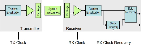
You can model three major sources of jitter using the STAT mode in the Parallel Link Designer: TX clock jitter, RX clock jitter, and RX clock recovery jitter. You can also add RX noise.
Jitter and noise affect the bit error rate (BER) of a serial channel. Some sources of jitter affect the data bathtub curve and some affect the clock PDF (probability distribution function). The data bathtub and clock PDF are used in the BER calculation, so changing either changes BER.
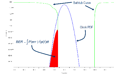
TX jitter and RX noise always change the data eye and data bathtub. RX jitter and RX clock recovery jitter are handled differently depending on how you set the Clock Mode parameter.
Normal — RX clock recovery jitter affects the clock PDF.
Clocked — RX clock recovery jitter affects the data eye and bathtub.
Convolved — RX clock recovery jitter affects the data eye and bathtub.
To access jitter and noise parameters, first select a transfer net sheet by selecting Setup > TNet Properties. Then open the Designator Element Properties panel by selecting Properties. Finally, open the parameters by selecting Tx Jitter or Rx Jitter. These dialog boxes are also accessible by double clicking any of the designators in the Pre-Layout Analysis tab.
TX Clock Jitter
The app models the TX clock jitter using five parameters. The parameters modify the Tx stimulus (Time Domain analysis) or are added in postprocessing (Statistical Analysis). View and modify these parameters in the TX Jitter dialog box, accessible through the Designator Element Properties dialog box.
TX jitter always changes the data eye and data bathtub.
| Jitter Parameter | Description |
|---|---|
| Tx Rj | Random Gaussian-distributed jitter (RJ) injected at the transmitter. The level is defined as the standard deviation of the RJ, in unit intervals (UI) or seconds. This is sometimes used to model the effects of power supply noise generated by logic switching events in the core of the device. Tx Rj affects the stimulus as follows:
Time(n) = n
× UI +
Time(n) is the time of edge n.
|
| Tx Dj | Deterministic jitter (DJ) injected upstream of the link. The level is defined as peak DJ, in UI or seconds. Tx Dj accounts for all deterministic and uncorrelated bounded jitter that is not accounted for by Tx DCD and Tx Sj. DJ is applicable only on the transmit side. The effects of intersymbol interference in the transmission channel are accounted for directly in the analysis or simulation. Tx Dj affects the stimulus as follows:
Time(n) = n
× UI +
|
| Tx Sj | Sinusoidal jitter (SJ), or sinusoidally varying delay injected at the transmitter. SJ is one half peak-to-peak deviation, in UI or seconds. This is sometimes used to model the effects of power supply noise generated by clock currents in the core of the device. Tx Sj affects the stimulus as follows:
Time(n) = n
× UI +
If Tx Sj Frequency is not defined, then Tx Sj is ignored. |
| Tx Sj Frequency | Tx Sj Frequency is used explicitly in time domain simulation. Otherwise, Tx Sj Frequency is assumed to be much higher than the bandwidth of the clock recovery loop. Tx Sj Frequency is specified in Hz. |
| Tx DCD | Transmission duty cycle distortion (DCD) is defined as the difference in
symbol duration between one symbol and the next. The value is the length of the
logic
Time(n) = n
× UI +
|
Note
If you set the TX jitter parameter in the AMI file, you cannot edit the field in the TX Jitter dialog box. To change the jitter, edit the AMI file.
When set to the format DjRj, the IBIS-AMI parameter
Tx_Jitter is translated to TX jitter parameters. The jitter parameter
includes the value of DjMax and DjMin. The parameters
are used to generate Tx_Dj and Tx_Rj:
There is also a shift in the stimulus in time domain analysis:
RX Clock Jitter
The RX clock jitter parameters modify the statistics of the recovered clock. These
parameters are used to account for jitter that is not included in either the
clock_times returned by Rx AMI_GetWave or the
Rx_Clock_Recovery parameters. These parameters are used by the
simulator when postprocessing the results from the model and are not passed to the model.
These parameters can be viewed and modified in the RX Jitter dialog box.
In the definition of these jitter parameters, time is the ideal clock
time in statistical analysis and in time domain analysis when Getwave does not exist.
time is the clock_time from Getwave when it exists
for time domain analysis.
| Jitter Parameter | Description |
|---|---|
| Rx Rj | Random Gaussian-distributed jitter (RJ) injected at the receiver. The level is defined as the standard deviation of the RJ, in unit intervals (UI) or seconds. This is sometimes used to model the effects of power supply noise generated by logic switching events in the core of the device. Rx Rj affects the clock times as follows:
clock_times(n) =
time +
|
| Rx Dj | Deterministic jitter (DJ), or the worst case half peak-to-peak variation of the recovered clock, not including the random jitter specified by Rx Rj, Rx Sj, or Rx DCD. Rx Dj includes all deterministic and uncorrelated bounded jitter that is not accounted for by Rx clock_times, Rx Rj, or Rx_Clock_Recovery parameters. Rx Dj affects the clock times as follows:
actual_time = time +
|
| Rx Sj | Sinusoidal jitter (SJ), or sinusoidally varying delay injected at the receiver. SJ is one half peak-to-peak deviation, in UI or seconds. This is sometimes used to model the effects of power supply noise generated by clock currents in the core of the device. Rx Sj affects the clock times as follows:
actual_time = time +
|
Rx_DCD | Duty cycle distortion (DCD) Difference in symbol duration between one
symbol and the next. Assume that the receiver is driven by a half-rate clock, with
symbols generated on the rising and falling edges of the clock, and further assume
that the duty cycle of that half-rate clock may not be exactly 50%. The value is
the length of the logic
actual_time = time +
|
Note
If you set an RX Jitter parameter in the AMI file, you cannot edit the field in the RX Jitter dialog box. To change the jitter, edit the AMI file.
When set to the format DjRj, the IBIS-AMI parameter
Rx_Clock_PDF is translated to Rx clock recovery jitter parameters.
The jitter parameter includes the value of DjMax and
DjMin. The parameters are used to generate
Rx_Clock_Recovery_Dj and
Rx_Clock_Recovery_Rj:
There is also a shift in the stimulus in time domain analysis:
RX Clock Recovery Jitter
Parallel Link Designer models RX clock recovery jitter using these parameters. This data is used when postprocessing the results from the model. Statistical analysis always uses these parameters. Time domain analysis uses these parameters when the model does not return clock_times or when Rx AMI_GetWave does not exist. These parameters add to any jitter from the RX jitter parameters. Add these parameters to the AMI file using a text editor.
When defining these jitter parameters, ideal_time is defined as the halfway between the median of the eye crossing 0.0 on both sides of the eye.
| Jitter Parameter | Description |
|---|---|
| Rx Clock Recovery Mean | Mean phase of recovered clock with respect to the center of the eye diagram (one half symbol from the median data transition time) in unit intervals (UI) or seconds. Rx Clock Recovery Mean affects the clock times as follows:
actual_time = ideal_time +
|
| Rx Clock Recovery Rj | Random Gaussian-distributed jitter (RJ), injected at the clock recovery circuit. The level is defined as the standard deviation of the RJ, in UI or seconds. This is sometimes used to model the effects of power supply noise generated by logic switching events in the core of the device. Rx Clock Recovery Rj affects the clock times as follows:
actual_time = ideal_time +
|
| Rx Clock Recovery Sj | Sinusoidal jitter (SJ), or sinusoidally varying delay injected at the clock recovery circuit. SJ is one half peak-to-peak deviation, in UI or seconds and a modulation frequency. This is sometimes used to model the effects of power supply noise generated by clock currents in the core of the device. Rx Clock Recovery Sj affects the clock times as follows:
actual_time = ideal_time +
|
| Rx Clock Recovery DCD | Duty cycle distortion (DCD) is defined as half the peak-to-peak variation, in UI or seconds, of a clock duty cycle distortion exhibited by the recovered clock. Rx Clock Recovery DCD affects the clock times as follows:
actual_time = ideal_time +
|
RX Noise
RX noise parameters modify the statistics associated with the data input to the sampling latch of the receiver. This data is used by Parallel Link Designer when postprocessing the results from the model; the budget values specified by the parameters are not passed directly to the model itself.
| Noise Parameter | Description |
|---|---|
| Rx Noise | Standard deviation, in volts into a 100 ohm differential load, of a set of independent samples of a Gaussian noise process measured at the sampling latch of a receiver. Rx Noise is Gaussian distributed amplitude noise at the receiver decision point. It is assumed that the samples of this noise process are independent of each other in what is often called an additive white Gaussian noise (AWGN) process. Typically, this noise is generated by shot noise in the receive amplifier. It is seldom if ever accurate to model crosstalk or power supply noise as a Gaussian distributed process. In order to supply an accurate value for this parameter, it might be necessary to account for the gain of the receive amplifier and any analog equalization inserted before the receiver decision point. Rx Noise affects the clock times as follows:
wave(t) =
wave(t) +
Note Rx GaussianNoise replaces the Rx Noise parameter in the IBIS specification (version 7.0). However, you can use either.
|
| Rx Uniform Noise | Worst-case half peak-to-peak variation, in volts, of a bounded uniform random process. This is added to the signal measured at the sampling latch of a receiver. |
| Rx Noise Pad | Spectral density of the AWGN at the input to a receiver buffer in volts/sqrt(Hz). Ignored for a driver. Add this parameter to the AMI file using a text editor. |
Note
If you set an RX Noise parameter in the AMI file, you cannot edit the field in the RX Jitter dialog box. To change the jitter, edit the AMI file.
Set Jitter and Noise in AMI File
You can set jitter and noise parameters in multiple ways depending on the models and the type of simulation. The table shows sample AMI file entries.
| Parameter Type | Sample Entry and Description |
|---|---|
| Value |
The Transfer Net Properties dialog box shows the values, but editing is disabled to indicate that the value is controlled by the AMI file. |
| Corner |
The value used in the analysis is based on the IC process corner selected in the GUI. The Transfer Net Properties dialog box shows <AMI Corner> in the cell for parameters defined in the AMI file as Corner. |
| Range |
The parameter will appear in the solution space table and can be swept. The Transfer Net Properties dialog box shows <Sweep> in the cell for parameters defined in the AMI file as Range. |