Crosstalk Analysis with Serial Link Designer
This example shows how to perform pre-layout crosstalk analysis using the Serial Link Designer app.
Open the example project sldCrosstalkExample.
openSignalIntegrityKit("sldCrosstalkExample");
Project Setup
Schematic Sheets
The example project contains three schematic sheets: an uncoupled single channel sheet and two multi-channel schematic sheets. The example channel runs at 100 Gbps.
The 1_Single_Channel sheet consists of a transmitter driving 8-inches of stripline trace, then traversing through a via to a top layer where microstrip traces connect AC-coupling caps to the receiver pins.

The multi-channel sheets have the same topology with the exception that there is a victim channel with aggressor channels on both sides. The multi-channel sheets are called 2_Crosstalk_DSE_Semi and 3_Crosstalk_DSE_Explicit.

To simplify reporting of results and minimize data, you can choose to only report the results for the victim channel receiver RX1. To do so, double click on any of the designators on the sheet to open the Designator Element Properties dialog box. You can select which receivers generate reports from the last column.
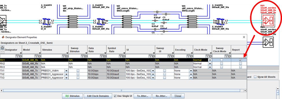
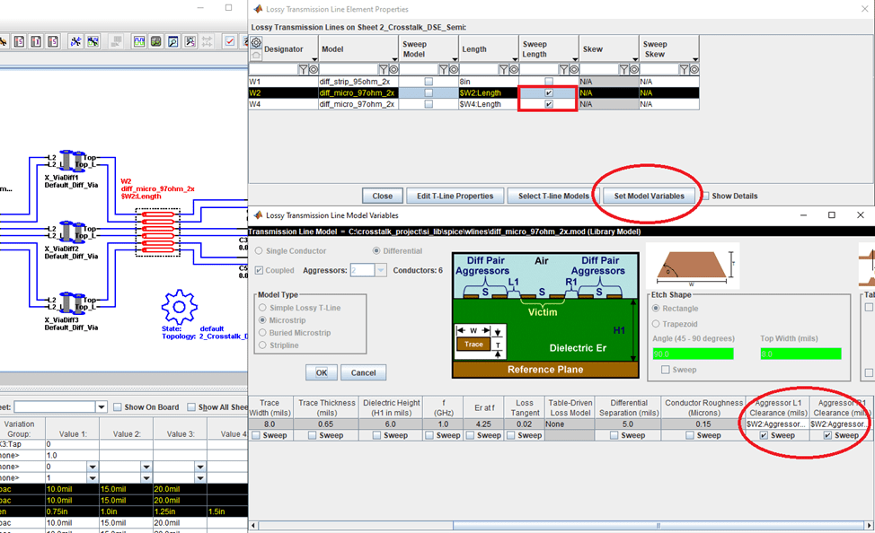
To set up the microstrip lines, you can double click on any of the transmission lines on the schematic to open the Lossy Transmission Line Properties dialog box. You can select the lines to sweep their lengths.
For the multi-channel schematics, both the length and clearance of the microstrip lines are varied. From the Lossy Transmission Line Properties dialog box, click the Set Model Variables button to open the Lossy Transmission Line Model Variables dialog box. You can select to sweep the aggressor clearance between the microstrip traces (W2 and W4 only).
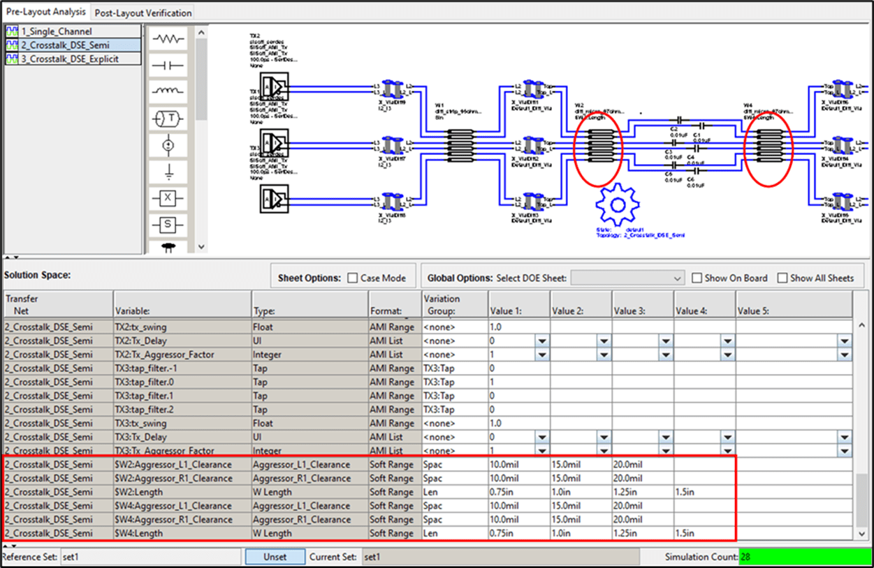
After verifying the setup and closing the dialog boxes, you can see the solution space area is populated with both the length and aggressor clearance variables. In this project the length is varied from 0.75 inch to 1.5 inches with 0.25-inch increments. The aggressor clearance varies from 10 mils to 20 mils with 5 mils increments.
Variation Groups
A variation group allows you to control the combinations of variable values that to simulate. By associating two or more rows with the same variation group name, you can lock those variations to sweep together. In the figure below there are two variation groups employed in the solution space, one for length (Len) and one for clearance between transmission lines (Spac). Using variation groups reduces the number of simulation cases from 1296 to 12 for each of the multi-channel sheets (4 lengths X 3 clearances). Since the single channel does not have any aggressors, only the Len variation group is used. This results in 4 simulation cases. Thus, the total simulation count for all sheets in this project is (12 + 12 + 4 = 28). For more information on variation groups, see Solution Space.

Setup Rules Files
You can evaluate industry standard crosstalk metrics such as Integrated Crosstalk Noise (ICN), Power-Sum Xtalk (PSXT) and Integrated Crosstalk Ratio (ICR) using the Serial Link Designer app. To do this, you need to use the Rules Files. For more information about rules files, see Creating Compliance Masks in Serial Link Designer.
Open the Transfer Net Properties dialog box from Setup > TNet Properties. You can select a rule file to use from the Rules File column. Rules files apply to each transfer net. The Crosstalk rules file selected contains industry standard masks for ICN, PSXT, and ICR and an eye mask.

You can find the rules files in the <project_folder>\si_lib\rules.
Setup Stimuli
To perform time domain simulations, select the stimulus patterns for the victim and aggressor channels. Double click on any of the designators on a sheet to access the Designator Element Properties dialog. Click the IO Stimulus button to open the Stimulus dialog box. This is where you can define your own stimulus or edit an existing one. This project uses a PRBS31_Victim pattern as victim channel and a PRBS31_Aggressor pattern as aggressor channel respectively. These patterns are specifically set up for performing crosstalk analysis.

Time Domain Crosstalk Mode
The Serial Link Designer app offers two modes for crosstalk analysis: Semi-Analytic and Explicit. To select the crosstalk analysis mode, click Setup > Simulation Parameters to launch the Simulation Parameters dialog box.
In this project, 2_Crosstalk_DSE_Semi sheet is set up for semi-analytic crosstalk mode and 3_Crosstalk_DSE_Explicit sheet is set up for explicit crosstalk mode.

To set the simulation parameters independently for each of the schematic sheets, select the option Set by Sheet.
In Semi-Analytic crosstalk estimation, the app simulates each channel in the system in the absence of crosstalk. An eye diagram is accumulated using the recovered clock to set the timing. The app separately calculates the probability density function (PDF) of the crosstalk. The app then convolves the crosstalk PDF with the eye diagram and generates a bathtub curve and the bit error rate estimate. Use this method to predict the crosstalk effect on the eye to very low probabilities.
In Explicit time domain simulation, all channels in the system are simulated simultaneously in the time domain so that the waveform at the receiver decision point is the combined result of the desired signal and the crosstalk aggressors. A bathtub curve is accumulated over the course of the simulation, using the recovered clock to set the timing. Choose this analysis method to see the bit-by-bit effect of the crosstalk noise from the aggressors to the victim channel.
Run the simulation after verifying the settings.
Simulation Results
After the simulations are complete, the app launches Channel Analysis results spreadsheet and the Signal Integrity Viewer app with simulation results loaded. The Channel Analysis Log tab of the channel analysis report reveals the reporting for the ICN (integrated crosstalk noise) rule. This report shows a pass/fail indication for each simulation result where the ICN rule is applied.
Signal Integrity Viewer
This example project contains a configuration file (siviewer.cfg) to plot various simulation results. You can open the configuration file From File > Open Configuration in the Signal Integrity Viewer app.
Network Analysis Results
Select the Network tab at the bottom left of the viewer and view the four columns ICR, ICN, PSXT, and unEq Signal/Xtalk.

Network Tab Columns Setup
Organize the columns within this tab to make only the columns of interest visible.
Select the gear icon to the left of the Row column header. This opens the Table Column Control dialog box.
Right click and select Set All Invisible to turn off all columns.
Select the ICR, ICN, PSXT, SDD21, $W2:LENGTH, and $W2:AGGRESSOR_L1_CLEARANCE options.
To order the columns, select a row or rows and use the arrows at the top of the dialog.
Click Apply and OK.

This view is also saved in the project as network_table_view which you can select from the Selected Table View dropdown menu. For more information about saving table views, see Managing Simulation Data and Results.
After customizing the view for the Network tab, the app shows only the columns of interest. Use the wildcard 2 at the top of the Transfer Net column to show only the results from the 2_Crosstalk_DSE_Semi sheet.
The results shown for ICR, ICN and PSXT in the table are the margin to each of their respective masks, not the actual values. A red colored result indicates that it has a negative margin to the mask.

To plot the ICR:
Select the results rows corresponding to the 10 mil clearance in the $W2:AGGRESSOR_L1_CLEARANCE in the table.
Right-click to see the plot options. At the bottom of the menu are the rules for ICR (Insertion loss to crosstalk ratio), ICN, and PSXT. Select Show ICR (dB) from the menu.
The left side of the viewer window lists four plots. Select the four plots, right-click and select Color Selected Waveforms.
Select a red color.
Repeat the process for the 15 mil results (blue) and 20 mil results (green).
Add a title and subtitle (optional).
Rename the display by selecting the Display1 tab on the left side of the window and right-click. Select Rename “Display1”. Name the display
ICR.
The ICR plot for the 2_Crosstalk_DSE_Semi sheet is shown.

The x-axis is the frequency and the y-axis is the plotted ICR in decibels (dB). ICR is a representation of the ratio of signal to the crosstalk. The three colors of the plotted results are based on the Aggressor Clearance setting ($W2:AGGRESSOR_L1_CLEARANCE) where red is 10 mil, blue is 15 mil and green is 20 mil. The four curves that are plotted for each clearance represent the four different coupling lengths ($W2:LENGTH) that were simulated. The black curve is the ICR mask from the rules file. Results that plot on or above the mask have a better signal-to-noise ratio and would meet or exceed the mask requirements. The plot indicates that the 20 mil clearance plots in green meet the mask requirement for all of coupling lengths. Whereas only some of the blue and none of the red meet or exceed the mask limit.
Next, plot ICN by first creating a new display:
Right click on the ICR display tab and select Add New Display.
Follow the same steps as before except select Show ICN_OIF and name the display ICN.

ICN is a measure of the crosstalk noise to the loss of the channel (SDD21). The mask is plotted in black, and each color represents a coupling clearance for the four different settings for the microstrip traces. With this mask, results that plot at or below the mask meet or exceed the requirements. The plot shows that only a few of the results meet the mask requirement. The green markers which represent the widest coupling clearance (20mil) shows three of the four settings exceed the mask requirement.
Create a new display as before and plot PSXT.
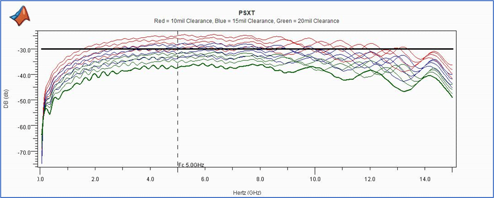
PSXT is a measure of the coupled noise, or crosstalk between channel against frequency. The mask is set at -30dB and the results are once again grouped based on coupling clearance. The green plots represent the 20 mil coupling clearance and all are below the mask limits. Two of the blue (15mil) results appear to meet the mask also. None of the red (10mil) clearance results are within mask limits across the frequency band.
The UnEQ Signal/Xtalk is a metric that Serial Link Designer measures when performing Network Analysis. UnEQ Signal/Xtalk is the unequalized signal to the measured crosstalk as a ratio in decibels (dB). This is measured at the Nyquist Frequency of the design.
Looking at the results in the table below it has a variation from approximately 24 dB to almost 36 dB. Although ICR, ICN and PSXT are different metrics, all are essentially signal-to-noise ratios. For this design an UnEQ Signal/Xtalk value of above 31dB correlates to meeting any of the other masks.
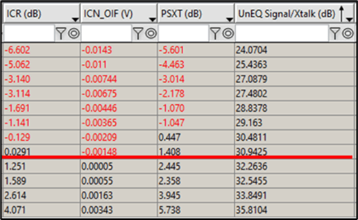
You can visualize the correlation between UnEQ Signal/Xtalk and ICR, ICN, and PSXT using the viewer in Plots mode. This viewer mode allows the user to plot any two metrics or variables against each other.
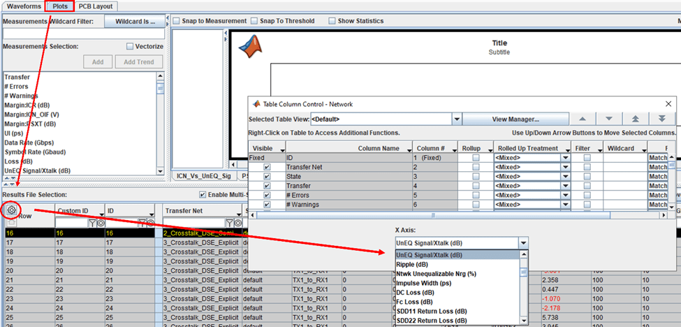
Select the Plots tab in the upper left corner of the viewer window.
Select the gear icon to open the Table Column Control dialog box. Select
UnEQ Signal/Xtalkfrom the X Axis dropdown menu.Select all the rows for the 2_Crosstalk_DSE_Semi sheet.
Right click and select ICN.
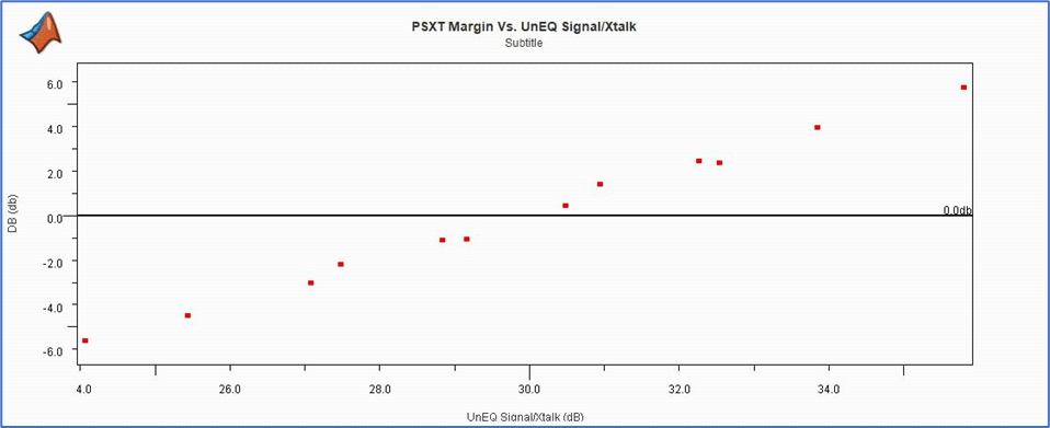
The resulting plot shows the correlation between UnEQ Signal/Xtalk and ICN margin. Approximately 32 dB correlates to meeting the ICN margin. The black line represents zero margin or meeting the mask.

Follow the same step as before to plot ICR and PSXT against UnEQ Signal/Xtalk. The plots below show similar correlation to UnEQ Signal/Xtalk as ICN.

Statistical Analysis Results
To view statistical analysis results, select the Statistical tab.
To access the saved table view statistical_table_view for the columns click the gear icon on the Row column header. The result has the only the columns checked below. It also has the Transfer Net filter checkbox checked and the wildcard 2 in the box as shown.

Set the $W2:LENGTH (in) column wildcard box to 1.0 to display only the coupling lengths of 1 inch.
Note the columns named SkewEyeMask_die_Inner (V) and SkewEyeMask_die_Inner (UI). These are the margins to the eye mask applied to the statistical eye at the die pad of the victim receiver. The margin represents the closest point on the mask to the inner eye contour. The eye mask is one of the rules discussed earlier and it is applied to both the statistical and time domain results in the project.
To plot the statistical eye with the eye mask applied:
Select row 2 of the sorted results.
Select Show Statistical Eye.
Then right click on the row and select SkewEyeMask_die.
Below is the statistical eye diagram for the 2_Crosstalk_DSE_Semi sheet where the coupling length is 1.0 inch and the coupling clearance is 10mil. The eye mask from the rules file is applied to the eye.

You can compare the statistical eye from the 1_Single_Channel sheet (top) against the statistical eye just plotted. To create this plot:
Add a new display.
Plot the statistical eye from the 1_Single_Channel transfer net.
Plot the statistical eye from row 2.
Next select the Split View icon in the toolbar at the top of the screen.
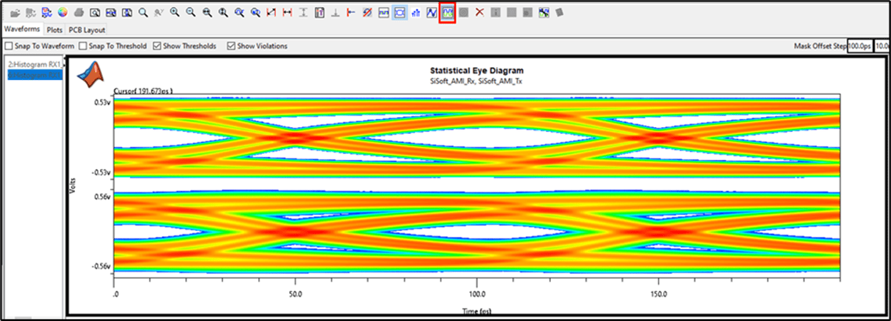
Comparing the two eyes shows that there is eye closure due to crosstalk in the 2_Crosstalk_DSE_Semi eye (bottom plot) when compared with the 1_Single_Channel eye.
You can look at the crosstalk as a histogram, which is what is applied to the statistical eye to create the eye closure. To plot this:
Add a new display.
Select the row 2 results.
Right click and select Show Crosstalk.

The crosstalk histogram is also used in the time domain Semi-Analytic crosstalk mode on the persistent eye.
Time Domain Analysis Results
Time domain results with respect to crosstalk analysis focus on either Semi-Analytic or Explicit modes. Sheet 2_Crosstalk_DSE_Semi simulations use the semi-analytic mode and Sheet 3_Crosstalk_DSE_Explicit uses the explicit mode.
Create a new display.
Select the Time Domain tab in the lower left corner of the viewer window.
Select the gear icon in the first column.
In the Selected Table View dropdown menu, select
time_domain_table.Note the wildcards for Transfer Net, $W2:LENGTH and $W2:AGGRESSOR_L1_CLEARANCE.
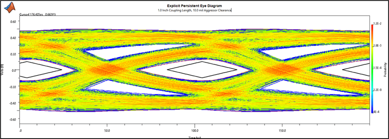
The filtering parses out two rows of results shown above. The results for 1.0-inch coupling length and 10-mil aggressor clearance for Semi-Analytic crosstalk mode and for Explicit time domain crosstalk mode.
Select row 1 and right-click.
Select Show Persistent Eye.
Next select Show SkewEyeMask_die.

Follow the same steps as before to plot the persistent eye and mask for row 2. This is the persistent eye using Explicit crosstalk mode. The explicit time domain crosstalk mode reveals the effect of the user defined aggressor bit pattern on the victim waveform instead of the statistical crosstalk histogram. This plot only shows the number of time domain bits simulated (excluding any ignore bits required for the model).
Lastly, you can observe how Explicit and Semi-Analytic modes compare using the time domain waveform. The time domain waveform consists of only the recorded bits from the simulation. This comparison requires the 1_Single_Channel, 2_Crosstalk_DSE_Semi, and 3_Crosstalk_DSE_Explicit waveforms.
Create a new display.
Remove the wildcard filter on the Transfer Net column and the $W2:AGGRESSOR_L1_CLEARANCE. The 1_Single_Channel result and all of the 2_Crosstalk_DSE_Semi and 3_Crosstalk_DSE_Explicit results for 1.0-inch length will be populated in the results.
Now plot the 1_Single_Channel waveform. Then the 2_Crosstalk_DSE_Semi and 3_Crosstalk_DSE_Explicit waveforms in rows 2 and 5.
Using the horizontal zoom, zoom in to show approximately 20 bits of the waveforms.

The red and blue waveforms are 1_Single_Channel and 2_Crosstalk_DSE_Semi respectively. The two waveforms overlay each other. This is expected behavior with the Semi-Analytic crosstalk mode as the statistical crosstalk histogram is applied to the persistent eye to represent the coupled result. So no bit-to-bit coupling is applied to the semi-analytic time domain waveform. The green waveform is from the 3_Crosstalk_DSE_Explicit sheet and the differences show where the signal is affected by the coupling from aggressor channels.