Channel Operating Margin (COM)
Channel Operating Margin (COM) is a figure of merit for a passive channel expressed in decibels. COM gives insight about the quality of the passive channel design. It is calculated using the ratio of signal amplitude factors to noise amplitude factors. Channel bit rate, insertion loss, return loss, cross-coupling, transmitter and receiver equalization, and IC package models are some of the factors applied to determine COM. While it is required for compliance in some applications, COM can also be a valuable part of channel design methodology in general.
The IEEE® 802.3ck defines the channels operating at 106.247Gbps PAM4 meaning a symbol rate of 53.124Gbaud. These channel designs can involve PCB only, backplane or copper cables. Signaling is accomplished with either NRZ (Non Return to Zero) or PAM4 (Pulse Amplitude Modulation). Encoding the packets with forward error correction (FEC) is optional but can greatly improve a channel BER (Bit Error Ratio). Testing the compliance of the passive electrical channel to the specification requires it to meet or exceed what is known as COM (or Channel Operating Margin) as measured in decibel units.
COM is a figure of merit derived from the scattering parameters of the passive channel. Its calculation relies on the s-parameter models of the victim and aggressor channels along with user specified information about the TX, RX and their equalization characteristics. COM can also account for the package characteristics of the TX and RX or you can choose to define generic package characteristics to be used in the COM calculation.
A series of MATLAB® application scripts have been developed to automate the COM calculations. The scripts are offered for download on the IEEE website (e.g. com_ieee8023_93a.m). To maintain continuity for those utilizing this application, Signal Integrity Toolbox™ integrated the capability of running COM through the Serial Link Designer app. Its implementation provides direct interface with MATLAB and a seamless process of passing the appropriate s-parameter channel models. All COM results are consolidated into one report and select COM results from the report can be added to the Channel Analysis report and thus are directly loaded into the Signal Integrity Viewer tool after a COM simulation. You can then use these metrics in the analysis of the channel.
The COM code is a statistical based algorithm which is based on linear time invariant (or LTI) assumptions about the channel, transmitter and receiver. A complete channel design flow would include simulating the interface using TX and RX IBIS-AMI and package models of the actual silicon both statistically and in time domain with an objective of meeting a target BER (Bit-Error-Ratio). This can only be accomplished using a channel simulator such as Serial Link Designer.
Signal Integrity Toolbox offers a variety of compliance and design kits.
Channel Design Methodology
COM can be used as a fast and easy way test signal-to-noise performance of a channel regardless of compliance to a specification. The channel being designed can be an 802.3ck implementation or a custom design. It could implement NRZ or PAM4 signaling. You can set a multitude of parameters with limits unique to your design and use those values to determine COM.
An example of channel design methodology can be shown as:
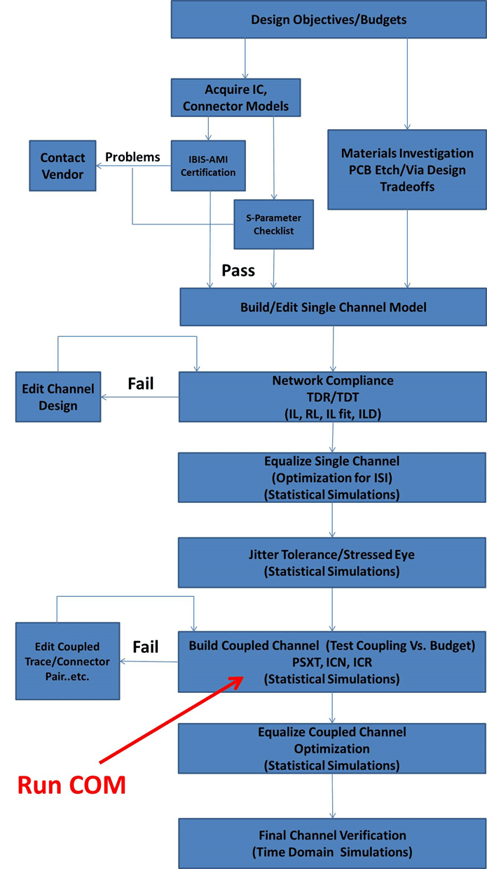
The highlighted area can benefit from using COM as part of design analysis.
COM Setup
The COM configuration spreadsheet is a specially formatted document and is used to define each of the variables required to run COM. Some of the settings are unique to the channel and others are user preferences or control settings.

Note
The COM script is a continuously changing piece of software as new specifications are adopting this methodology and new metrics and tests are being added. Please visit the IEEE website (https://www.ieee802.org/3/ck/public/tools/index.html) to download the latest COM code, example spreadsheets, and documentation
Channel S-parameters for COM
Along with the spreadsheet, the other input to the COM code is the measured or simulated s-parameter models of the victim channel and its aggressors. A coupled channel model is shown:
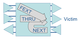
There is a victim channel (Thru) and two aggressors showing the far-end (FEXT) and a near end (NEXT) coupling to the victim. Models of the victim and each aggressor are passed into COM as 4-port S-parameter models. There is virtually no limit to the number of aggressor channels passed into COM. However, from a practical standpoint 2-3 aggressors on each side of the victim will account for most of the crosstalk. Serial Link Designer automatically extracts these models during the “Network Analysis” simulation and when running COM simulation. The appropriate s-parameters and parameters are automatically passed into the COM script.
Viewing COM Results
There are many results outputted by COM. All of the COM results from a simulation are available in the Collected COM Results report. To access the report, in the Serial Link Designer, select Reports > Collected COM Results Report.
Any of the results from the COM simulation can be preselected for display in the Channel Analysis Report. This loads the results in the Signal Integrity Viewer after simulation and allows them to be analyzed along with the standard simulation results. You can select the COM results that you want to add to the report by editing the “com_columns.txt” file which resides in the Serial Link Designer installation area. You can copy this file to your site configuration directory if you have one defined.
An example com_columns.txt file that demonstrates adding parameters
to the channel analysis report is shown:
Other than reporting COM the other parameters were chosen for demonstration purposes only. The parameters are defined as follows:
COM: COM value in dB for this case.
COM fit loss (dB): Fitted insertion loss at half baud rate.
COM FOM ILD: RMS over half baud rate span of insertion loss deviation. This may be used in the diagnosis of a channel design.
COM ICN (mV): RMS over half baud rate span of power sum of the crosstalk. This may be used in the diagnosis of a channel design.
COM TXLE taps: List of transmitter FFE taps used for the CTLE in the COM calculations.
COM FOM: Best figure of merit result from the CTLE and Tx FFE optimization.
COM DFE taps: Adapted DFE tap values.
CTLE DC gain (dB): DC gain of the CTLE after adaptation 0 to -12dB.
References
[1] IEEE P802.3ck 100 Gb/s, 200 Gb/s, and 400 Gb/s Electrical Interfaces, https://www.ieee802.org/3/ck/public/tools/index.html
[2] COM Configuration Documentation (config_com_ieee8023_93a_doc.pdf).