Model Floating-Tap Architectures in SerDes Systems
This example shows how to model a floating-tap FFE and DFE using SerDes Toolbox™ System objects. This example provides insights into the floating-tap architecture implementation and demonstrates the benefits of such architectures in SerDes systems.
In high-speed SerDes (Serializer/Deserializer) systems, maintaining signal integrity over long transmission lines is crucial. As data-rates increase, the challenges posed by channel impairments such as inter-symbol interference (ISI) become more pronounced. SerDes architects employ equalization techniques, including Feed-Forward Equalizers (FFE) and Decision Feedback Equalizers (DFE), to mitigate these impairments and ensure reliable data transmission.
Why Choose Floating Tap Architectures
A traditional FFE uses a fixed number of taps in fixed locations, which may not optimally address the varying nature of ISI across different channels. Similarly, a conventional DFE might struggle with channels exhibiting non-uniform ISI distribution. This is where floating-tap architectures have advantages over their fixed-tap counterparts. They allow dynamic adjustment of tap positions, providing greater flexibility and adaptability to the specific characteristics of the channel. This adaptability is particularly beneficial in scenarios where there is a reflective echo or when the channel conditions vary over time. By optimizing tap placement, floating-tap architectures can significantly enhance the equalization performance, leading to improved signal quality and reduced error rates.
How Floating Tap Architectures Work
In a floating-tap FFE, not all of the tap coefficients are confined to a fixed grid. Instead, they can be strategically placed to target specific points of ISI within the impulse response of the channel. This selective targeting allows the FFE to more effectively cancel out the ISI, improving the eye opening at the receiver.
Similarly, a floating-tap DFE can adaptively place its feedback taps to better address post-cursor reflections, which is crucial for minimizing the error propagation that can occur in decision-directed equalizers. By dynamically adjusting the tap positions, the DFE can more accurately compensate for the channel's specific ISI pattern.
Finding Optimal Tap Positions
Floating-tap implementations are typically defined by fixed taps at the beginning of the tap range followed by groups of floating taps. In most communication channels, the impulse response is strongest at the beginning and decays over time. This means that the most significant ISI effects are caused by symbols that are closest in time to the current symbol being processed. The early fixed taps in an equalizer are positioned to counteract these immediate ISI effects, which is why they often have higher values. The floating taps are defined by the valid tap positions for floating taps, how many groups are available and the size of the groups. Ideally, these tap groups are positioned where there is the greatest magnitude of energy to cancel in the response.
SerDes Toolbox provides a utility function called floatingTaps to find the best floating tap positions of a provided tap weight vector based on the number of fixed taps, total tap vector size, floating tap groups, and floating taps per group. This function identifies the best position for floating tap group(s) based on an input tap vector when ignoring fixed tap positions. Best position is defined as largest group sum when searching from left to right along the length of the tap weights vector. This operation is repeated for each group. To define the floating taps, in the MATLAB® command window, type:
taps = serdes.utilities.floatingTaps(optimizedTaps, fixedTaps, groups, groupSize)
where,
optimizedTapsis the vector of tap weights before floating tap constraints are applied. The size of the vector controls the range of floating tap positions.fixedTapsis the number of leading tap weights to ignore. When using with an FFE, include the pre-taps and main tap.groupsis the number of floating tap groups.groupSizeis the size of each floating tap group.
To see how the function works, create a vector of random taps between -0.2 and 0.2. This is input to the floatingTaps functions with the constrains of 2 fixed taps, 2 tap groups, and 2 taps per group. Then plot the before and after tap positions.
rng(1)
optimizedTaps = -0.2 + (0.4) * rand(1, 20)
optimizedTaps = 1×20

   -0.0332    0.0881   -0.2000   -0.0791   -0.1413   -0.1631   -0.1255   -0.0618   -0.0413    0.0155   -0.0323    0.0741   -0.1182    0.1512   -0.1890    0.0682   -0.0331    0.0235   -0.1438   -0.1208
floatingTaps = serdes.utilities.floatingTaps(optimizedTaps,2,2,2)
floatingTaps = 1×20

   -0.0332    0.0881         0         0   -0.1413   -0.1631         0         0         0         0         0         0         0    0.1512   -0.1890         0         0         0         0         0
figure
nexttile
stem(optimizedTaps), title('Optimized Taps')
nexttile
stem(floatingTaps), title('Floating Taps')
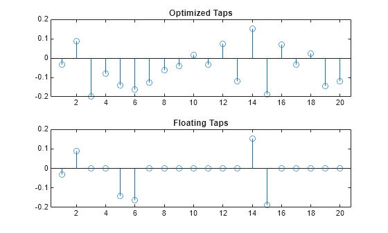
Observe that the function outputs a tap vector with two initial fixed taps and the largest two groups of two taps remaining. All other tap positions are zeroed out.
Integration in FFE and DFE System Objects
This example uses customized versions of the existing SerDes Toolbox System objects serdes.FFE and serdes.DFECDR. The customized classes, FFERxFloatingTaps.m and DFECDRFloatingTaps.m, are attached with this example.
For the FFE, the statistical portion of the FFE code is adapted using an algorithm implemented by the adaptFFE helper function. For more information about the adaptation technique, see ADC IBIS-AMI Model Based on COM example.
The resulting optimized tap weights feed the floating tap enforcement function which is configured with mask parameters for group specifications. The FFE applies the tap values for the statistical analysis then operates in fixed mode with the optimized taps from the statistical analysis for time domain analysis. Note that this FFE is intended only for use in a receiver as it needs all the upstream transmitter and channel characteristics included in the input impulse response.
For the DFE, since the statistical portion of the DFE code already contains an optimization function applying a zero forcing algorithm, you only require the floating tap enforcement function configured with mask parameters. As opposed to FFE, the DFE does continue to adapt in the time domain, so this required additional enforcement of the floating tap positions. This is accomplished by storing the non-zero tap positions passed from the statistical portion of the model and using those to continue zeroing out other tap positions.
For both the FFE and DFE, the valid tap positions that floating taps can be placed are controlled with the total amount of taps that are configured in the tap vector. This tap vector is typically provided via an IBIS-AMI parameter configured in the IBIS-AMI Manager and the resulting data store read created automatically.
You can observe the FFE and DFE changes in detail by comparing the code of the attached files with the installation versions.
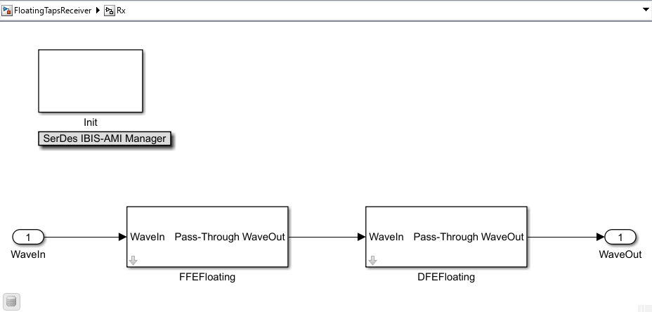
Configuring in SerDes Toolbox
Open the model FloatingTapsReceiver attached with this example. The model is pre-configured with both the FFE and DFE in the Rx. Both FFE and DFE are set up inside individual PassThrough blocks and connected to a set of IBIS-AMI parameters controlling Mode and Tap Weights. For more information on how to configure custom blocks, see Implement Custom CTLE in SerDes Toolbox PassThrough Block examples.
To access the floating tap settings, look under the mask of the PassThrough block and click on the MATLAB system block to open the individual system object masks. You can modify these parameters to fit any application. You must click the Refresh Init button after changing any of the mask based parameters as they are hardcoded in the Init code. The TapWeights IBIS-AMI parameter for both the FFE and DFE is configured with 60 taps allowing for the targeting of distant discontinuities. This wide tap span effectively sets the range of where the floating tap positions can be placed.
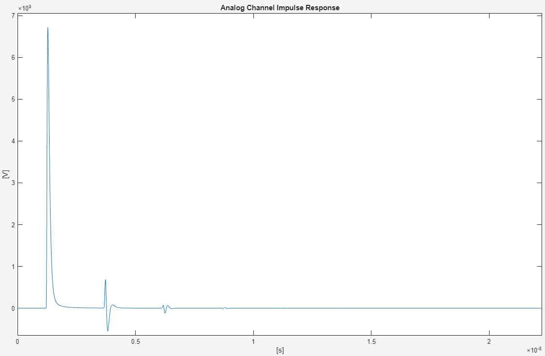
The channel is configured with a low loss and the analog models with unbalanced capacitance to cause several reflective impulse ripples in the impulse response tail. These ripples are perfect targets for canceling out with the floating taps. Actual measured channel models could have more and larger discontinuities to target with floating taps.
Simulation
To better observe the tap application in isolation, activate only one of the equalizer blocks is active at a time. You can activate both blocks for use at the same time, but this would be an atypical setup as the cancellation of distance reflection is only needed once in actual hardware.
For the example simulation, the FFE Mode is set to Adapt and the DFE Mode is set to Off. The FFE and DFE masks contain the floating tap settings defined in the above overview of the utility function floatingTaps. A FFE specific parameter was also added to denote the max value of a DFE tap 1 if used in conjunction with the FFE adaptation algorithm to prevent the FFE and DFE from using conflicting resources. Set this to 0 if not using a DFE or not concerned about limiting the FFE adaptation.
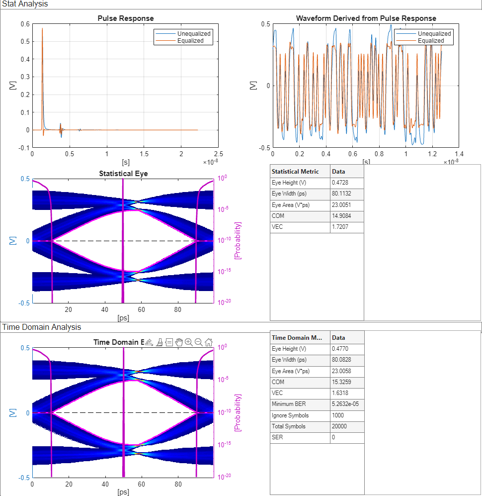
The eight fixed taps are in addition to the main tap and are intended to cancel out the initial lossy ISI in the channel where the three groups of four floating taps are targeted at the first and second reflective ripples shown in the impulse response earlier in the example. Run the model and observe the tap vector utilized in the Statistical analysis in the Simulink Diagnostic Viewer.
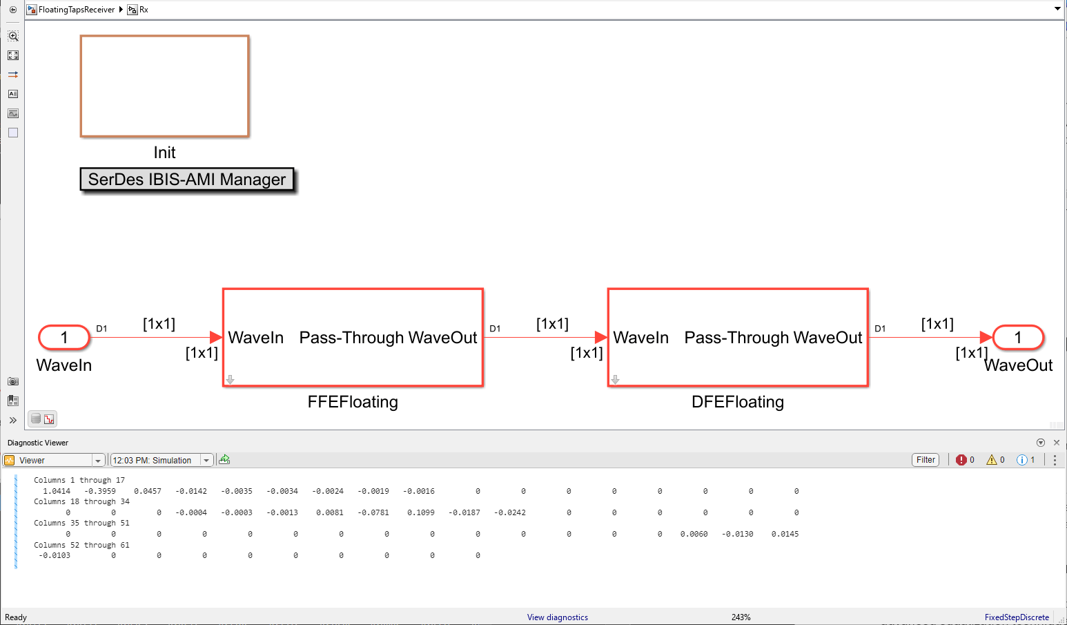
Note that two of the tap groups were ganged together to target the wider first ripple and the third group was applied on the small distance reflection. The FFE did well at canceling out most of the ISI as shown in the impulse response comparison.
Further Studies
Try disabling the FFE using the Mode parameter in the IBIS-AMI Manager and enabling the DFE. Note the slight differences in how the equalization is applied and the effectiveness of using the same configuration of floating taps.
Conclusion
This example explores the implementation and advantages of floating tap architectures in Feed-Forward Equalizers (FFE) and Decision Feedback Equalizers (DFE) using the SerDes Toolbox. By allowing dynamic adjustment of tap positions, floating tap architectures provide a robust solution to the challenges of inter-symbol interference (ISI) in high-speed communication channels.
Through strategic tap placement, these architectures enhance equalization performance, leading to improved signal integrity and reduced error rates. This adaptability makes floating tap FFEs and DFEs highly effective for a wide range of channel conditions, ensuring reliable data transmission in modern SerDes systems. By leveraging the capabilities of the SerDes Toolbox, you can effectively model and optimize floating tap architectures, paving the way for more efficient and resilient communication systems.