Model a CR-CR 4-Speed Transmission Driveline with Braking
The CRCRFourSpeedTransmissionExample example models a realistic
transmission. It uses a CR-CR 4-Speed transmission subsystem to transfer motion and
torque from one shaft and inertia to another.
CR-CR 4-Speed Transmission Model

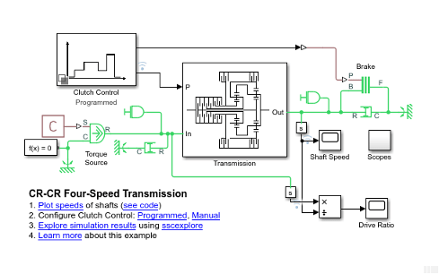
There is a constant driving torque from a torque source to the driver shaft (Inertia block on the left). Two damping subsystems apply heavy and light viscous friction to the driver and driven shafts, respectively. The two scope subsystems measure the clutch pressures. The model workspace defines essential parameters for the blocks. For information on creating, accessing, and changing model workspace variables, see Specify Source for Data in Model Workspace and Change Model Workspace Data.
The CR-CR 4-Speed transmission subsystem couples the driver to the driven shaft (Inertia block on the right). If the transmission is disengaged, a brake clutch and fixed housing allow you to brake the driven shaft.
For clarity, the major signal buses of the model have been bundled as vectors and directed using Goto and From blocks. The Clutch Pressures are collected in the Scopes subsystem for convenience.
Replacing Programmed with Manually Controlled Clutch Pressures
The model represents the clutch control system using a Variant Subsystem block. To switch between Programmed and Manual, the two clutch control modes that the variant provides, click the links in the model window. During simulation, the manual subsystem provides direct control over gear changes. To switch gears in manual control mode:
In the Simulink® toolbar, change the simulation time to
inf.Run simulation.
Change gears during using the Select Gear widget.
Manual Clutch Control for CR-CR Transmission

