Piston Engine
Reciprocating combustion engine with variable number of pistons

Libraries:
Simscape /
Driveline /
Engines & Motors
Description
The Piston Engine block represents a reciprocating combustion engine with multiple cylinders. The piston model accounts for the instantaneous torque transmitted to the engine drive shaft. The instantaneous torque enables you to model vibrations in the drivetrain due to piston revolution. To model just the piston mechanism of a combustion engine, use the Piston block.
Port B represents the engine block, and port F represents the rotating crankshaft. The piston force follows from the cylinder pressure and cross-sectional area. The block obtains the combustion pressure from a lookup table parameterized in terms of the crank angle and, optionally, the crank angular velocity and engine throttle level.
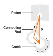
The crank torque follows from the piston force and crank angle as well as the crank and connecting rod lengths. In terms of these inputs, the ratio of the piston force and crank torque is
where:
FB is the instantaneous piston force associated with the base port.
TF is the instantaneous crank torque associated with the follower port.
c is the crank length.
θ is the instantaneous crank angle.
r is the connecting rod length.
Piston Dimensions
Physical signal port T lets you specify the engine throttle level as a fraction between 0 and 1. This fraction corresponds to the percentage of full power generated. The block uses the physical signal input whenever the pressure lookup table in the block property inspector is parameterized only in terms of the crank angle.
Ports
Input
Engine torque demand as a fraction of maximum possible torque.
Output
Fuel consumed by engine.
Conserving
Rotational mechanical conserving port associated with the engine block.
Follower port of engine. The crankshaft transmits the power generated from the combustion process. Typically, this is where you would attach a clutch and transmission.
Parameters
Pistons
Number of pistons in the combustion engine.
Vector of piston offset angles. The offset angle specifies the point in the engine cycle when the piston reaches top dead center. The engine cycle spans in angle from -S*180 to +S*180 degrees, where S is the number of strokes per cycle.
The vector size must be the same as the number of pistons. The default vector corresponds to a four-stroke, four-piston engine.
Inside diameter of the piston cylinder wall. The block uses this measurement to compute the torque table. You must specify a value greater than zero.
Distance from the fully retracted position to the fully extended position of the piston. The block uses this measurement to convert pressure on the piston into torque values. You must specify a value greater than zero.
Distance from the center of the piston pin hole to the center of the crankshaft hole in the piston rod. The block uses this measurement to convert pressure on the piston into torque. You must specify a value greater than zero.
Number of piston phases required to intake, compress, combust, and exhaust the combustion gases. Typically, engines are two-stroke or four-stroke. You must use a multiple of two.
Parameter group that you want the block to use to parameterize the pressure data.
Angle of the piston crank starting at or above the minimum angle and ending at or below the maximum angle. You can calculate the minimum or maximum angle by multiplying the number of strokes by -90 degrees or 90 degrees, respectively. You must specify at least two values.
Each element in Crank angle vector corresponds to an element in Pressure vector (gauge) or the M-row of Pressure matrix (gauge) or each Pressure 3D matrix (gauge) matrix.
Different throttle positions that correspond to the pressures in the Pressure matrix (gauge) or Pressure 3D matrix (gauge) parameters. The throttle position must remain in the range [0,1] with 0 representing no throttle and 1 representing full throttle.
Each element in Throttle vector corresponds to the N-column of Pressure matrix (gauge) or each Pressure 3D matrix (gauge) matrix.
Dependencies
To enable this parameter, set Pressure
parameterization to By crank angle and
throttle or By crank angle, throttle,
and crank velocity.
Different crank velocities that correspond to pressures in Pressure 3D matrix (gauge).
Each element in Crank velocity vector corresponds to one of the O-matrices of Pressure 3D matrix (gauge).
Dependencies
To enable this parameter, set Pressure
parameterization to By crank angle,
throttle, and crank velocity.
Vector of pressure values that correspond to different crank angle positions.
Dependencies
To enable this parameter, set Pressure
parameterization to By crank
angle.
Matrix of pressure values that correspond to different crank angle and
throttle combinations. The default value is [0, 0, 0, 0; 0, .9,
2.4, 3; 0, 6, 16, 20; 0, 15, 40, 50; 0, 6, 16, 20; 0, 3, 8, 10; 0,
2.4, 6.4, 8; 0, 0, 0, 0]
bar.
The elements of Crank angle vector correspond to the M-rows in Pressure matrix (gauge). The elements of Throttle vector correspond to the N-columns in Pressure matrix (gauge).
Dependencies
To enable this parameter, set Pressure
parameterization to By crank angle and
throttle.
Concatenated matrix of pressure values that correspond to the various
crank angle, throttle, and crank velocity combinations. The default
value is cat(3, [0, 0, 0, 0; 0, .9, 2.4, 3; 0, 6, 16, 20; 0,
15, 40, 50; 0, 6, 16, 20; 0, 3, 8, 10; 0, 2.4, 6.4, 8; 0, 0, 0, 0],
[0, 0, 0, 0; 0, .9, 2.4, 3; 0, 6, 16, 20; 0, 15, 40, 50; 0, 6, 16,
20; 0, 3, 8, 10; 0, 2.4, 6.4, 8; 0, 0, 0, 0], [0, 0, 0, 0; 0, .9,
2.4, 3; 0, 6, 16, 20; 0, 15, 40, 50; 0, 6, 16, 20; 0, 3, 8, 10; 0,
2.4, 6.4, 8; 0, 0, 0, 0])
bar.
The elements of Crank angle vector correspond to the M-rows. The elements of Throttle vector correspond to the N-columns. The elements of Crank velocity vector correspond to the matrices you concatenate along dimension O.
By default, M = 8, N = 4, and O = 3.
Dependencies
To enable this parameter, set Pressure
parameterization to By crank angle,
throttle, and crank velocity.
Crankshaft
Option to parameterize the shaft dynamics.
Viscous friction coefficients for the base bearing and follower bearing, in that order.
Crank angle at time zero relative to a top dead center position. The engine cycle spans in angle from -S*180 to +S*180 degrees, where S is the number of strokes per cycle.
Translational spring stiffness of engine crankshaft. The spring stiffness accounts for elastic energy storage in the crankshaft due to material compliance.
Stiffness coefficient of the engine crankshaft. This parameter accounts for resistance to shaft deformation.
Dependencies
To enable this parameter, set Shaft dynamics
to Specify shaft stiffness, damping, and
inertia.
Translational damping of engine crankshaft. The damping accounts for energy dissipation in the crankshaft due to material compliance.
Dependencies
To enable this parameter, set Shaft dynamics
to Specify shaft stiffness, damping, and
inertia.
Moment of inertia of crankshaft about its rotational axis. This parameter accounts for resistance to sudden changes in motion.
Dependencies
To enable this parameter, set Shaft dynamics
to Specify shaft stiffness, damping, and
inertia.
Deflection angle between the base and follower ends of the crankshaft at time zero. The deflection angle measures the angular deformation of the crankshaft due to torsion.
Dependencies
To enable this parameter, set Shaft dynamics
to Specify shaft stiffness, damping, and
inertia.
Angular velocity of the crankshaft at time zero.
Dependencies
To enable this parameter, set Shaft dynamics
to Specify shaft stiffness, damping, and
inertia.
Fuel Consumption
The table shows how the specified options for the Fuel consumption model parameter affects the availability of dependent parameters.
Fuel Consumption Parameter Dependencies
| Fuel Consumption | ||||
|---|---|---|---|---|
Fuel consumption model — Choose
No fuel consumption,
Constant per revolution,
Fuel consumption by speed and
										torque
, Brake specific fuel
consumption by speed and torque, or
Brake specific fuel consumption by speed and
brake mean effective pressure | ||||
| No fuel consumption | Constant per revolution | Fuel consumption by speed and torque | Brake specific fuel consumption by speed and torque | Brake specific fuel consumption by speed and brake mean effective pressure |
Fuel consumption per revolution | ||||
Speed vector | ||||
Torque vector | Brake mean effective pressure vector | |||
Fuel consumption table | Brake specific fuel consumption table | |||
Interpolation method —
Choose | ||||
Fuel consumption model based on available data. Select a model for calculating engine-fuel consumption. Model parameterizations are compatible with typical industrial data. Choose from the following options:
No fuel consumption— The default optionConstant per revolutionFuel consumption by speed and torqueBrake specific fuel consumption by speed and torqueBrake specific fuel consumption by speed and brake mean effective pressure
If you leave Fuel consumption model set to
No fuel consumption, the block does not
calculate fuel consumption even when the FC port is
connected to another block. Selecting this option increases simulation
speed.
Constant rate of fuel consumption as a function of crankshaft revolutions. Enter the volume of fuel consumed in one crankshaft revolution.
Dependencies
To enable this parameter, set Fuel
consumption to Constant per
revolution.
Vector of engine torques that corresponds to the M rows of the fuel consumption lookup table.
Dependencies
To enable this parameter, set Fuel
consumption to Fuel consumption by speed
and torque, Brake specific fuel
consumption by speed and torque, or
Brake specific fuel consumption by speed and brake
mean effective pressure.
Vector of engine torques that corresponds to the N columns of the fuel consumption lookup table.
Dependencies
To enable this parameter, set Fuel
consumption to Fuel consumption by speed
and torque or Brake specific fuel
consumption by speed and torque.
Matrix of fuel consumption values that correspond Enter matrix with
fuel consumption rates corresponding to engine speed and torque vectors.
The number of rows must equal the number of elements in the
Speed vector. The number of columns must equal
the number of elements in the Torque vector. The
default is [.5, .9, 1.4, 1.6, 1.9, 2.7, 3.4, 4.4; 1, 1.7, 2.7,
3.1, 3.6, 5, 6, 7.4; 1.4, 2.7, 4, 4.8, 5.6, 7.5, 8.5, 10.5; 2, 3.6,
5.8, 6.7, 8, 10.4, 11.7, 13.3; 2.5, 4.8, 7.9, 9.4, 10.8, 14, 16.2,
18.6; 3.1, 6, 10.3, 11.9, 13.8, 18.4, 22, 26.5]
g/s.
Dependencies
To enable this parameter, set Fuel
consumption to Fuel consumption by speed
and torque.
Vector of brake mean effective pressure (BMEP) values. The BMEP satisfies the expression:
where:
T is the output torque.
nc is the number of cycles per revolution.
Vd is the cylinder displaced volume.
Dependencies
To enable this parameter, set Fuel
consumption to Brake specific fuel
consumption by speed and brake mean effective
pressure.
For the Brake specific fuel consumption by speed and
torque fuel model, enter the matrix with brake
specific fuel consumption (BSFC) rates corresponding to engine speed and
torque vectors. BSFC is the ratio of the fuel consumption rate to the
output power. The number of rows must equal the number of elements in
the Speed vector. The number of columns must equal
the number of elements in the Torque vector.
For the Brake specific fuel consumption by speed and
brake mean effective pressure fuel model, enter the
matrix with brake specific fuel consumption (BSFC) rates corresponding
to engine speed and brake mean effective pressure (BMEP) vectors. BSFC
is the ratio of the fuel consumption rate to the output power. The
number of rows must equal the number of elements in the Speed
vector. The number of columns must equal the number of
elements in the Brake mean effective pressure
vector.
For both fuel-consumption models, the default is [410, 380,
300, 280, 270, 290, 320, 380; 410, 370, 290, 270, 260, 270, 285,
320; 415, 380, 290, 275, 265, 270, 270, 300; 420, 390, 310, 290,
285, 280, 280, 285; 430, 410, 340, 320, 310, 300, 310, 320; 450,
430, 370, 340, 330, 330, 350, 380]
g/hr/kW.
Dependencies
To enable this parameter, set Fuel
consumption to Brake specific fuel
consumption by speed and torque or
Brake specific fuel consumption by speed and brake
									mean effective pressure
.
Interpolation method to calculate fuel consumption at intermediate speed and torque values. Outside the data range, fuel consumption remains constant at the last value given in the lookup table for both methods.
Dependencies
To enable this parameter, set Fuel
consumption to Fuel consumption by speed
and torque, Brake specific fuel
consumption by speed and torque, or
Brake specific fuel
									consumption by speed and brake mean effective
									pressure
.
Extended Capabilities
C/C++ Code Generation
Generate C and C++ code using Simulink® Coder™.
Version History
Introduced in R2016a
MATLAB Command
You clicked a link that corresponds to this MATLAB command:
Run the command by entering it in the MATLAB Command Window. Web browsers do not support MATLAB commands.
Select a Web Site
Choose a web site to get translated content where available and see local events and offers. Based on your location, we recommend that you select: .
You can also select a web site from the following list
How to Get Best Site Performance
Select the China site (in Chinese or English) for best site performance. Other MathWorks country sites are not optimized for visits from your location.
Americas
- América Latina (Español)
- Canada (English)
- United States (English)
Europe
- Belgium (English)
- Denmark (English)
- Deutschland (Deutsch)
- España (Español)
- Finland (English)
- France (Français)
- Ireland (English)
- Italia (Italiano)
- Luxembourg (English)
- Netherlands (English)
- Norway (English)
- Österreich (Deutsch)
- Portugal (English)
- Sweden (English)
- Switzerland
- United Kingdom (English)