DVB-S2X Link Simulation with RF Impairments and Corrections for Super-Frame Formats 6 and 7
R2026bThis example shows how to generate and receive DVB-S2X super-frame (SF) format 6 and 7 Waveforms, as defined in ETSI EN 302 307-2 Annex E [1]. The example performs DVB-S2X link-level simulation, including waveform generation, transmission across multiple beam-hopping dwells, synchronization, and bit recovery. At the receiver, the example uses start of super-frame (SOSF) detection based on differential correlation to locate super-frame boundaries, estimates frequency offset from the correlation peak phase, and recovers transmitted data using iterative Low-Density Parity-Check (LDPC) and Bose–Chaudhuri–Hocquenghem (BCH) forward error correction (FEC) decoding.
The example also demonstrates receiver re-acquisition at dwell boundaries, where a postamble terminates the current beam-hopping transmission and forces the Synchronizer to return to search state. While the example configures a format 6 waveform, the helper objects also support format 7, which uses a simplified super-frame structure containing only SOSF and pilot fields.
Super-Frame Structure
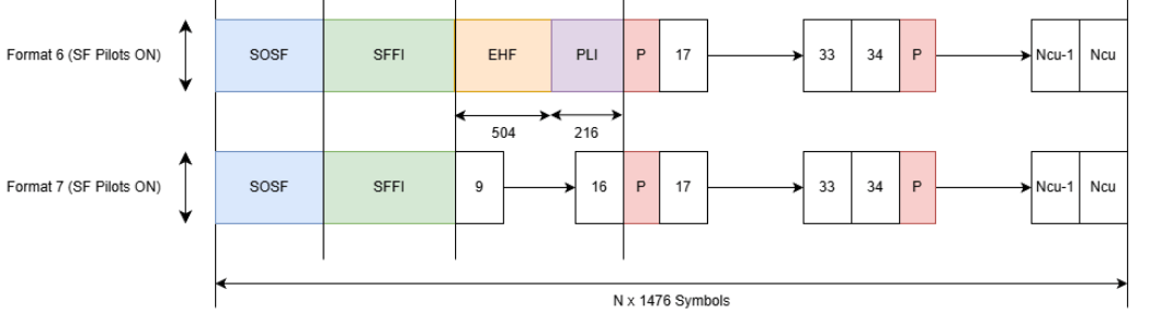
The super-frame structure provides better support for synchronization algorithms compared to the regular DVB-S2X frames using several SF-specific fields, such as SOSF, Super-Frame Format Indicator (SFFI), and SF-aligned pilots, to enhance receiver performance. The structure for formats 6 and 7 is of a variable-length, in multiples of 1476 symbols, and hosts DVB-S2X and DVB-S2 physical layer frames (PLFRAME) with modified physical layer header (PLH) fields.
The first field in the SF is the SOSF, which is 270 symbols in length.
The second field is the SFFI, which is 450 symbols in length.
The third field is an extended header field (EHF), which is 504 symbols in length and contains format-based information. Format 7 does not contain this field.
The fourth field is the PLH protection level index field (PLI), which is 216 symbols in length and indicates the maximum protection applied to the PLHs in the super-frame. Format 7 does not contain this field.
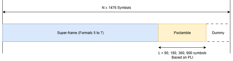
The last field, attached to the last SF in a dwell, is a postamble whose length varies based on Physical-Layer Header (PLH) protection levels.
The remaining portion of the SF consists of DVB-S2/S2X and the SF-aligned pilots.
An SF-wide scrambling technique scrambles all symbols in an SF using two scramblers. The reference scrambler scrambles the SOSF and the SF-aligned pilots. The payload scrambler scrambles the SFFI, EHF, PLH, PLI fields, and PLFRAMEs.
The structure divides the format-specific content section of the SF into resource slots called capacity units (CU). Each CU is 90 symbols in length and contains the PLFRAME symbols. The SF length is N*1476 symbols, where N is an integer. The waveform generator places Pilot fields (P) in the SF at a periodicity of 16 CUs. Alternatively, the SF length N*1440 symbols if the waveform generator does not use pilots when using format 5.
These figures show the SF structure for formats 6 and 7:
The last SF in a dwell includes a postamble symbol sequence during beam switching. This sequence indicates that the satellite is about to switch off the current beam. The SF contains the postamble and transmits it before the end of a dwell duration. This figure shows the SF structure with the postamble.
This example demonstrates how to parameterize and generate several SF for a specific beam over multiple dwells that cover a singular cell, and perform receiver operations to observe the performance of the SFs. You can perform synchronization and bit recovery of the transmitted PLFrames.
SOSF, SFFI, Pulse-Shaping, and Scrambling Properties of SF
Generate the SF using the HelperSuperFrameGenerator5to7.m object, and set its parameters.
Format— Set to6, or7.SOSFIndex— Select the appropriate Walsh-Hadamard sequence, in the range [0, 255], to use as the SOSF.Pulse-shaping Parameters — These include
SamplesPerSymbol,RolloffFactor, andFilterSpanInSymbols.ScramblingCodeNumbers— Select the Nth gold code for generating the scrambling sequence for the reference and the payload scramblers. The property accepts a row vector of length two, [Nref Npayload]. The value of N is in the range [0, 148574].
sfWaveGen = HelperSuperFrameGenerator5to7; sfWaveGen.Format =6; sfWaveGen.SOSFIndex =
0; sfWaveGen.ScramblingCodeNumbers = [14 26]; sfWaveGen.RolloffFactor =
0.35; sfWaveGen.FilterSpanInSymbols = 10; sfWaveGen.SamplesPerSymbol = 4;
SF-Aligned Pilots and PLI Properties
These properties signal the pilot and reference sequences to be used.
PilotIndex— Select an appropriate Walsh-Hadamard sequence, in the range [0, 31], to use as the pilot sequence.PLHProtectionIndex— Specify the PLH protection levels to determine the repetition factor of the PLHs in each PLFRAME.SuperFrameLength— Specify the SF length as an integer multiple of 1476 symbols.EHFSequenceIndex— Select an appropriate Walsh-Hadamard sequence, in the range [0, 252], to use as the extended header field sequence. This property is valid for only format 6.
sfWaveGen.PilotIndex = 1; sfWaveGen.PLHProtectionIndex = 1; sfWaveGen.SuperFrameLength = 1476*20; if isequal(sfWaveGen.Format,6) sfWaveGen.EHFSequenceIndex =0; end
DVB-S2/S2X Frames Properties
These properties generate the PLFRAMEs that constitute a SF.
StreamFormat— Set as either "TS" or "GS", corresponding to transport stream and generic stream, respectively.PLSDecimalCode— Physical layer signaling, specified as a decimal value. This property is applicable whenSuperFrameModeis set to "Regular". The valid values for this property are listed in ETSI EN 302 307-1 section 5.5.2.2 and ETSI EN 302 307-2 section 5.5.2.2 Table 17a.DFL— Data field length.
sfWaveGen.StreamFormat = "TS";
sfWaveGen.PLSDecimalCode = 86;
sfWaveGen.DFL = 13072;
symbolRate = 90e6;
sfInfo = sfWaveGen.getSuperFrameInfo(sfWaveGen.PLSDecimalCode, symbolRate, ...
    sfWaveGen.SuperFrameLength / symbolRate);
numPLFramesPerSF = floor(sfInfo.numCUPerSF / sfInfo.CUReqPerPLF);
Initialize the random number generator with a seed. Vary the seed to obtain different input data. The value used here, 73, is arbitrary.
seed = 73;
rng(seed);
Receiver Setup
Configure the Synchronizer to detect the SOSF and estimate frequency offset. The synchronizer operates as a streaming receiver front end and supports both SF formats 6 and 7. Because all SF formats contain SOSF and pilot fields, the synchronization algorithms are common across formats. For format 6, the Format property accounts for the EHF, SFFI, and PLI overhead when calculating frame boundaries. For format 7, the payload follows the SOSF directly.
The Synchronizer performs these operations.
SOSF detection — The Synchronizer constructs a composite reference from the known SOSF, SFFI, and pilot Walsh-Hadamard sequences and performs differential correlation for detection of the SF start index.
Timing error detection (TED) and correction — The synchronizer leverages references fields to execute TED and apply the compensate the symbol timing offset on the payload fields.
Frequency offset estimation and compensation — The phase angle of the differential correlation peak provides a frequency estimate, which the Synchronizer uses to compensate the frequency error.
The bit-recovery module performs the following steps.
Physical layer descrambling — Reverse the Gold-code scrambling applied to the transmitted symbols.
SFFI decoding — Recover the SF format.
PLI decoding — Determine PLHeader repetition factor.
PLHeader recovery — Apply convolutional decoding using the Viterbi algorithm to recover the physical layer signaling signaling parameters from the protected PLHeader.
xFECFrame recovery — Extract the complex FEC frame by performing deinterleaving, LDPC decoding (with early termination), BCH outer decoding, and CRC verification.
% Impairments - configure the set of impairments to be applied to the
% generated waveform
EsNodB = 12;
% Initialize the synchronizer object
sfSync = HelperDVBS2XSFSynchronizer;
sfSync.Format = sfWaveGen.Format;
sfSync.Mode = "Regular";
sfSync.SOSFIndex = sfWaveGen.SOSFIndex;
sfSync.PilotIndex = sfWaveGen.PilotIndex;
sfSync.EHFSequenceIndex = sfWaveGen.EHFSequenceIndex;
sfSync.ScramblingCodeNumbers = sfWaveGen.ScramblingCodeNumbers;
sfSync.NumPilotsForSync = 1;
sfSync.SamplesPerSymbol = sfWaveGen.SamplesPerSymbol;
sfSync.MinSuperFrameLength = sfWaveGen.SuperFrameLength-270;
sfSync.SymbolRate = symbolRate;
disp(sfSync);
  HelperDVBS2XSFSynchronizer with properties:

                     Format: 6
                       Mode: "Regular"
                  SOSFIndex: 0
      ScramblingCodeNumbers: [14 26]
                 PilotIndex: 1
           NumPilotsForSync: 1
           EHFSequenceIndex: 0
           SamplesPerSymbol: 4
              DampingFactor: 1
    NormalizedLoopBandwidth: 0.0100
               DetectorGain: 2.7000
        MinSuperFrameLength: 29250
                 SymbolRate: 90000000
% Initialize the bit recovery helper object
sfBitRec = HelperDVBS2XSFBitRecoverer;
sfBitRec.ScramblingCodeNumbers = sfWaveGen.ScramblingCodeNumbers;
DVB-S2X SF Synchronization and Frame Recovery
The receiver operates in a streaming architecture, processing the waveform in blocks of one pilot period of 1476 symbols. This approach models a practical satellite receiver that performs continuous synchronization and frame recovery on incoming data.
The receiver operates in these states.
Acquisition — The synchronizer continuously computes a differential-correlation metric on each received block. When the metric exceeds the detection threshold, the synchronizer declares an SOSF and transitions to the tracking state.
Tracking — The synchronizer filters incoming waveform and passes synchronized symbols to the bit recovery module. The bit recovery module maintains state across successive blocks and assembles complete PLFrames from the incoming symbol stream.
SF Boundary Handling — When the synchronizer detects a new SOSF, it identifies a SF boundary. The bit recovery module flushes any partially assembled frame and resets its internal state before processing symbols from the new SF. This mechanism preserves frame boundaries even when PLFrame boundaries do not align exactly with SF boundaries.
Dwell Reacquisition — The outer processing loop iterates across multiple dwells. After detecting a postamble at the end of a dwell, the receiver resets the synchronizer and bit recovery modules and returns to the acquisition state. This behavior models beam-hopping systems in which the receiver must reacquire synchronization at the start of each new dwell.
% Create variables for storing receiver statistics
totalFramesDecoded = 0;
totalFramesLost = 0;
% Initialize dwell parameters
numDwells = 2;
numSuperFrames = 1;
samplesPerSymbol = sfWaveGen.SamplesPerSymbol;
for dwellIdx = 1: numDwells
    % reset waveform generator, synchronizer, and bit recovery objects
    reset(sfSync);
    reset(sfBitRec);
    reset(sfWaveGen);
    % initialize state parameters for the current dwell
    sosfDetectedInDwell = false;
    numPLFramesThisDwell = numPLFramesPerSF*numSuperFrames;
    dwellWaveform = [];
    % Iterative generation of waveform for a single dwell
    for PLFIndex= 1:numPLFramesThisDwell
        tsn = mod(PLFIndex,254); % Unique TSN per frame
        % Generate all PLFrames for this dwell
        data = sfWaveGen.generateInputData;
        terminateDwell = (PLFIndex==numPLFramesThisDwell);
        [sfOutputFiltered,sfOutputSymbols] = sfWaveGen(data,tsn,terminateDwell);
        if terminateDwell
            dwellWaveform = [dwellWaveform; sfOutputFiltered; sfWaveGen.flushFilter]; %#ok<AGROW>
        else
            dwellWaveform = [dwellWaveform; sfOutputFiltered]; %#ok<AGROW>
        end
    end

        % --- Channel Impairments ---
        % Add AWGN
        nVar = 10^(-EsNodB/10);
        dwellWaveform = awgn(dwellWaveform,EsNodB-10*log10(samplesPerSymbol),"measured");

        % --- Receiver Processing ---
        % Feed waveform through the synchronizer
        % The synchronizer will scan through the dwellWaveform to identify
        % the SOSF. The synchronizer will set SOSFFLAG to true when it
        % detects an SOSF in the current waveform input.
        [symBlock,sosfFlag] = sfSync(dwellWaveform);

        if sosfFlag
            % When SOSF is detected, the bit recovery module is reset to
            % clear all buffers and reset its scramblers, and to perform
            % SFFI and PLHeader decoding alongside symbol descrambling.
            reset(sfBitRec);
            fprintf("SOSF detected\n");
            sosfDetectedInDwell = true;
            % Feed detected block into bit recover
            [bits,frameSuccess,~] = sfBitRec(symBlock,nVar);
            if ~isempty(bits)
                % Update statistics on frame success and loss
                totalFramesDecoded = totalFramesDecoded + frameSuccess;
                totalFramesLost = totalFramesLost + ~frameSuccess;
            end
        elseif ~isempty(symBlock)
            % Normal block pass-through after SOSF lock - the bit recovery
            % module loads the incoming symbols into the bit recovery
            % buffers and continue xFECFrame recovery
            [bits,frameSuccess,~] = sfBitRec(symBlock, nVar, false);
            if ~isempty(bits)
                totalFramesDecoded = totalFramesDecoded + frameSuccess;
                totalFramesLost = totalFramesLost + ~frameSuccess;
            end
        end
        % Generate warning if the SOSF is not detected in a dwell
    if ~sosfDetectedInDwell
        fprintf(" Warning: SOSF not detected in dwell %d\n", dwellIdx);
    end
end
Super-Frame Number 1 is being generated.
Super-Frame Number 1 is complete.
Dwell Complete
SOSF detected
Super-Frame Number 1 is being generated.
Super-Frame Number 1 is complete.
Dwell Complete
SOSF detected
fprintf("\n=== Results ===\n");=== Results ===
fprintf("Total FEC frames decoded: %d\n", totalFramesDecoded);Total FEC frames decoded: 12
fprintf("Total frames lost: %d\n", totalFramesLost);Total frames lost: 0
Supporting Files
This example uses these supporting files.
HelperSuperFrameGenerator5to7.m: Generate DVB-S2X SF waveform samples for formats 6 and 7.
HelperDVBS2XSFSynchronizer: Process received waveform and perform initial SF synchronization.
HelperDVBS2XSFBitRecoverer: Perform bit recovery from DVB-S2X SF waveform for formats 6 and 7.
References
ETSI EN 302 307-2 V1.4.1 (2024-08), "Digital Video Broadcasting (DVB); Second generation framing structure, channel coding and modulation systems for Broadcasting, Interactive Services, News Gathering and other broadband satellite applications; Part 2: DVB-S2 Extensions (DVB-S2X)"

