DVB-S2 Bent Pipe Simulation with RF Impairments and Corrections
This model shows a bent pipe satellite link that transmits a Digital Video Broadcasting Satellite Second Generation (DVB-S2) [5] signal from a first ground station to a satellite. The satellite receives the analog signal, amplifies and filters it without demodulation, then retransmits it to a second ground station. That ground station demodulates and decodes the signal, and a testbench calculates the end-to-end packet error rate (PER) and a low density parity check (LDPC) coding bit error rate (BER).
Introduction
The model creates a DVB-S2 signal that includes:
Bose-Chaudhuri-Hocquenghem (BCH) encoding
LDPC encoding (normal and short frame) [6], [7]
Interleaving
Modulation (QPSK, 8PSK)
The model also optionally applies multiple RF impairments to the signal on the uplink and downlink, and can also optionally correct them. These impairments include:
Equation-based and table-based memoryless nonlinearities [1]
Doppler error
Receiver thermal noise [4]
Analog filter effects
Phase noise [2], [3]
Amplitude and phase imbalances
DC offset
This example combines the modeling done in the following examples:
Refer to these examples to gain the background necessary to understand this bent pipe example.
Model Overview
This example loads a MAT file with DVB-S2 LDPC parity matrices. If the MAT file is not available on the MATLAB® path, then the example downloads them from mathworks.com. Internet connectivity is required to perform this download operation.
The model is shown in the following figure:

The ground station transmitter and uplink path are shown in the top half of the model, and the satellite repeater on the right side of the model. The downlink and ground station receiver are shown in the bottom half of the model. You can change parameters by interacting with the Model Parameters block.
The Model Parameters block enables you to update uplink, satellite, and downlink parameters separately. In particular, the block enables you to specify the diameters of the ground station and satellite transmit and receive antennas. With the block you can also set the noise figures of the satellite and the receiving ground station analog front ends.
The Model Parameters block also enables you to define in-phase/quadrature (I/Q) amplitude imbalance in dB, I/Q phase imbalance in degrees, and an in-phase DC offset as a percentage of the mean received in-phase signal amplitude.
The model also enables multiple visualizations:
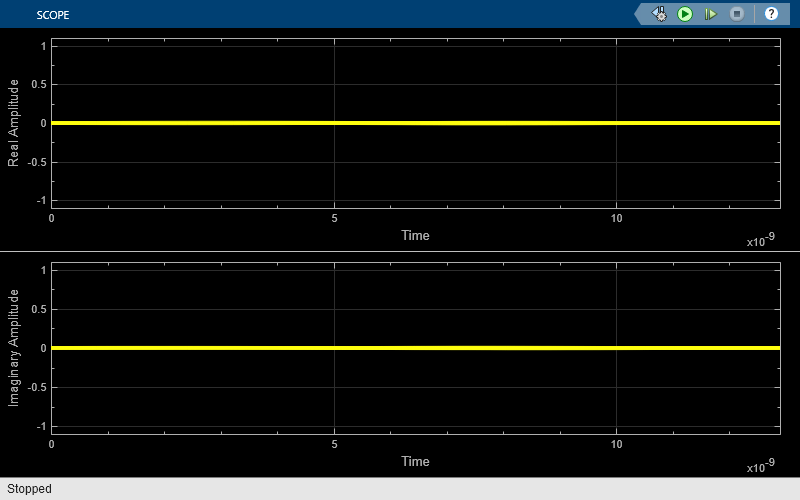
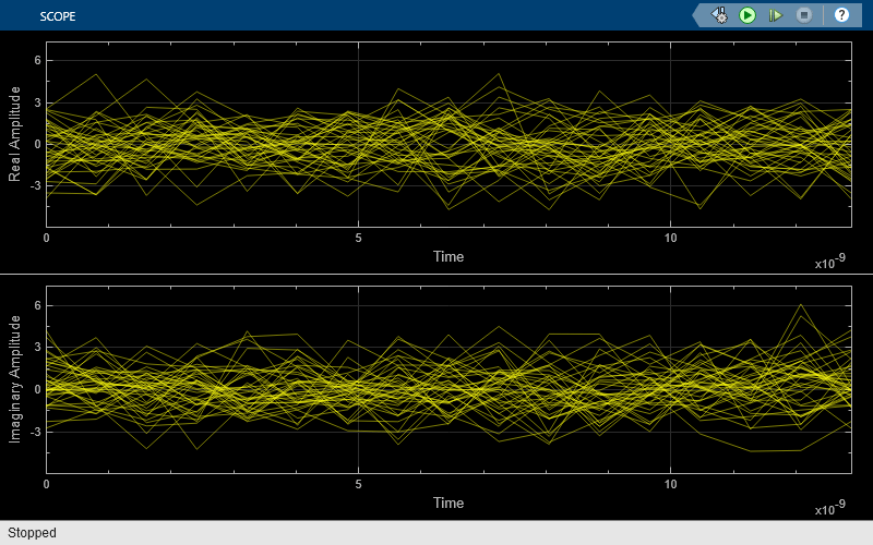
Power spectra
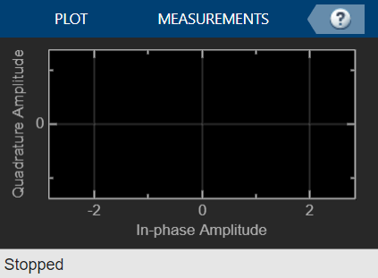
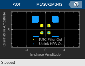
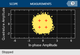
Constellation diagrams
Eye diagrams
AM/AM and AM/PM curves to show nonlinearity effects
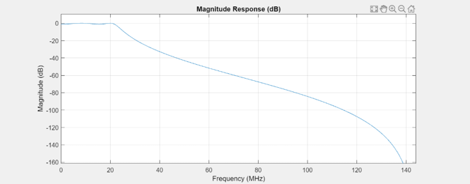
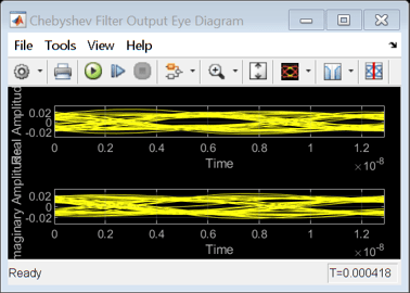
The satellite repeater includes several operations not found in the two examples referenced above. First, the repeater models an analog Chebyshev filter to reduce the noise in the signal received by the satellite. You can examine the filter characteristics using the freqz function.
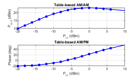
Also, the satellite repeater employs an amplifier that uses a table-based memoryless nonlinearity. You can use the "Plot Power Characteristics" button of the Onboard Processing/HPA Nonlinearity block to generate AM/AM and AM/PM plots for the amplifier. The following figure shows the amplifier AM/AM and AM/PM characteristics.
The soft decision QPSK or 8PSK demodulator requires an estimate of the noise variance at its input in order to properly calculate the approximate log-likelihood ratios. The model performs a realistic variance calculation by comparing the received signal against the ideal constellation and calculating error vectors between them. When the noise and other distortions are sufficiently small, the variance calculation is accurate. When the impairments increase such that received constellation points cross over into adjacent, incorrect decision regions, the variance calculation will be overly optimistic.
Simulation Results
Run the example to see the following run-time visualizations:
Power spectra of the transmit and receive ground station signals, and at multiple points during the satellite onboard processing


AM/AM and AM/PM characteristics of the uplink power amplifier


Constellations before and after the uplink amplifier, and during onboard processing

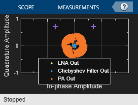

Received constellation at the ground station input

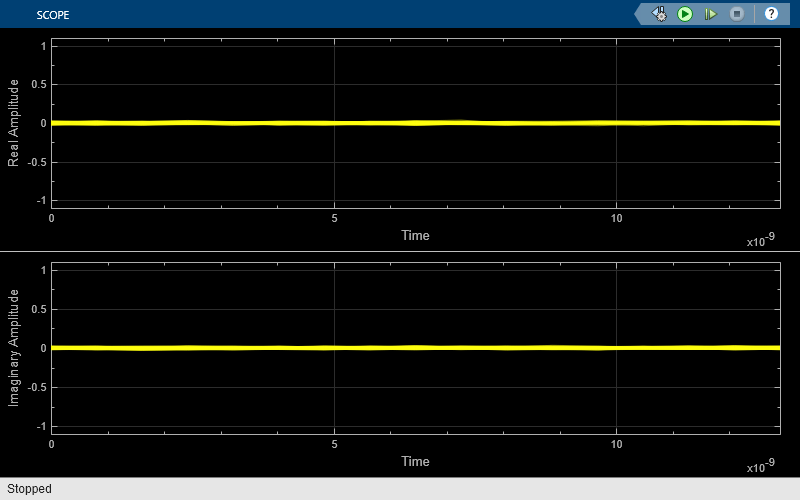

Eye diagrams before and after the onboard Chebyshev filter, and at the ground station receiver input


In addition, during run time you can inspect the signal power at the transmitting ground station antenna, the satellite receiver antenna output, the satellite low noise amplifier (LNA) output, and the satellite transmit antenna output.
Further Exploration
You can experiment with the example in the following ways:
Change modulation and coding formats to determine when the BER unacceptably degrades for a given signal-to-noise ratio (SNR) scenario.
Turn on single distortions to qualitatively and quantitatively determine their impact on PER and BER.
Enable RF corrections to ensure that they restore signal quality and PER.
Reduce the SNR to a level where the RF corrections are no longer effective.
Navigate to the
RF Correctionssubsystem and tune the parameter values of the individual blocks in the subsystem, such as theCarrier Synchronizeror theDC Blocker.Increase the Chebyshev filter order to determine if the increased group delay distortion affects PER.
Reduce the satellite amplifier backoff factor to examine its effect on SNR and PER.
Instead of a geostationary altitude of 35,600 km, change the satellite altitude to a MEO altitude of 20,000 km or a LEO altitude of 2,000 km. Examine how the antenna sizes can then be reduced, or the receiver noise figure can be increased.
Experiment with different uplink and downlink frequencies.
Investigate the effect of digital predistortion (DPD) on PER when the uplink amplifier is driven into its saturation region.
Bibliography
[1] Saleh, A. A. M. "Frequency-Independent and Frequency-Dependent Nonlinear Models of TWT Amplifiers." IEEE Transactions on Communications, Vol. 29, No. 11, Nov. 1981.
[2] Kasdin, N.J. "Discrete Simulation of Colored Noise and Stochastic Processes and 1/(f^alpha); Power Law Noise Generation." Proceedings of the IEEE, Vol. 83, No. 5, May 1995.
[3] Kasdin, N. J., and T. Walter "Discrete Simulation of Power Law Noise ." Proceedings of the 1992 IEEE Frequency Control Symposium, IEEE 1992.
[4] Sklar, Bernard, and Fredric J. Harris. Digital Communications: Fundamentals and Applications. Englewood Cliffs, NJ: Prentice-Hall, 1988.
[5] ETSI Standard EN 302 307 V1.1.1(2005-03). Digital Video Broadcasting (DVB); Second Generation Framing Structure, Channel Coding and Modulation Systems for Broadcasting, Interactive Services, News Gathering and other Broadband Satellite Applications.
[6] Gallager, Robert. "Low-Density Parity-Check Codes." IRE Transactions on Information Theory, Vol. 8, No. 1, Jan. 1962: 21-28.
[7] W. E. Ryan, "An Introduction to LDPC Codes." in Coding and Signal Processing for Magnetic Recoding Systems (Bane Vasic, ed.). CRC Press, 2004.