Verify Code by Using Co-Simulation and a SoftPLC
In this example, you verify IEC 61131-3 Structured Text code by using co-simulation and a software-based programmable logic controller (SoftPLC). You build and simulate a verification model in Simulink® and run the Structured Text code on a CODESYS SoftPLC. The verification model uses Simulink OPC UA blocks to communicate with and retrieve the data from the SoftPLC.
Prerequisites
You must install:
CODESYS 3.5 SP 16+ or later
Industrial Communication Toolbox™
Before you import the XML files, you must verify the CODESYS IDE version and the DeviceIdentification parameters. To verify the IDE version and DeviceIdentification parameters, in the CODESYS IDE, click Tools > Device Repository > PLCs > CODESYS Control Win V3 x64 and then click Details. This image shows the Device Repository details in the CODESYS IDE.
Manually verify that the device repository details match the details in the XML files. This image shows the information to match in the XML files:

You must match the Type, Id, and Version information. If the information does not match the Device Repository details, you must manually change these fields before you import the XML files.
Open Models
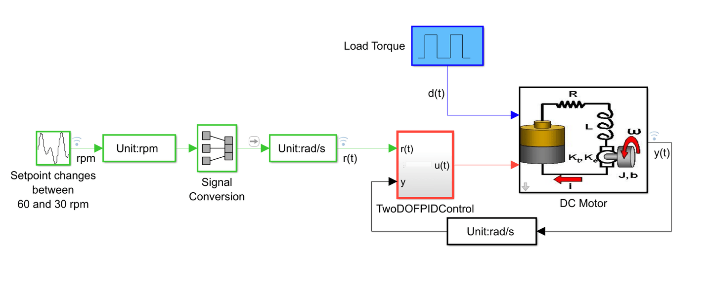
The plc_cosim_rt and plc_cosim_sync models contain:
An input signal that simulates revolutions per minute (RPM) changes
A
TwoDOFPIDControlsubsystem block that contains OPC UA Read and Write blocks that read and write data for a two-degree-of-freedom PID control algorithm running on the CODESYS SoftPLCAn armature-controlled DC motor block.
In the plc_cosim_rt model, the TwoDOFPIDControl subsystem block contains OPC UA Read and Write blocks that read and write data for a two-degree-of-freedom PID control algorithm.
open_system("plc_cosim_rt");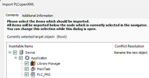
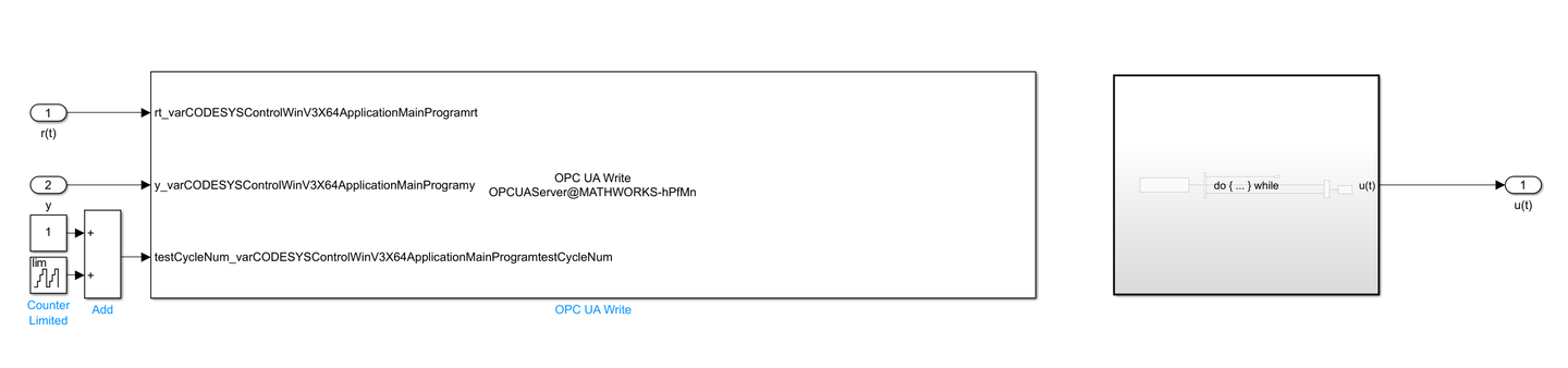
In the plc_cosim_sync model, the TwoDOFPIDControl subsystem contains a While Iterator subsystem block that synchronizes the cycle numbers.
open_system("plc_cosim_sync");
Choose a Co-Simulation Strategy
You can choose between performing independent co-simulations or a synchronized co-simulation. Independent co-simulations offer the advantages of:
Flexibility, because you can simulate each subsystem at its own natural time step
Performance, because you can optimize each component individually
Modularity, because it is easier to integrate and replace subsystems without affecting others
Independent co-simulations require more data interaction handling than synchronized co-simulations, which can result in numerical mismatch problems. Use independent co-simulation when the subsystems operate at vastly different time scales, are loosely coupled, and when you want to prioritize performance and modularity over accuracy.
Synchronized co-simulations offer the advantages of:
Data consistency, because the subsystems exchange data at the same time steps
Stability, because the components update synchronously, which reduces the risk of numerical mismatch errors
Simplified integration, because data exchanges are not complex
Compared to independent co-simulations, synchronized co-simulations have significant performance overhead, reduced flexibility, and use complex code to synchronize the accurate data exchanges at each time step. Use synchronized co-simulations when high accuracy and data consistency are more critical, when systems are tightly coupled and need precise interactions, and when system dynamics are similar across subsystems.
In independent co-simulations, the Simulink model and CODESYS program run at different rates. In addition, you must run the Simulink model in simulation pacing mode, which allows you to slow the simulation to help analyze and interact with your model. In synchronized co-simulations, the model adds a cycle number at each time step to ensure that data is not lost during read or write operations. The CODESYS model runs at a faster sampling rate and the Simulink model runs in normal simulation mode. This table demonstrates which CODESYS file and Simulink model to choose based on your choice of co-simulation mode.
Simulation Mode | CODESYS PLCopen XML File Name | Simulink Model Name |
independent |
|
|
synchronized |
|
|
Configure CODESYS for OPC UA Communications
Open CODESYS and create a new project. Select Standard project. Set the project name to either
plc_cosim_rtorplc_cosim_sync. Set Device toCODESYS Control Win3 x64 (CODESYS)and set PLC_PRJ in toStructured Text (ST).Select the project name and click Project > Import PLCopen XML. Select the import file based on your simulation mode. For independent simulation, select
plc_cosim_rt.xml, and for synchronized simulation, selectplc_cosim_sync.xml.Select Device and click OK.

4. Right-click Device (CODESYS Control Win3 x64), and select Delete. Under Device_1 ,select Application.
5. Right-click Application and select Add Object > Symbol Configuration. Select Support OPC UA features. Click Add.
6. Click Build. Select PLC_PRJ. For plc_cosim_rt, set the Access Rights as shown in this table. To change the access rights, click in the Access Rights column until the symbol matches the symbol in this table.
Signal Name | Access Rights Icon | Access Right Granted |
rt |
| Write only |
ut |
| Read only |
y |
| Write only |
For plc_cosim_sync, set Access Rights as shown in this table. To change the access rights, click in the Access Rights column until the symbol matches the symbol in this table.
Signal Name | Access Rights Icon | Access Right Granted |
rt |
| Write only |
ut |
| Read only |
y |
| Write only |
previousCycleNum |
| Read and write |
testCycleNum |
| Read and write |
7. Enable anonymous user access to the OPC UA server. Start the SoftPLC by selecting CODESYS Control Win SysTray - x64 from the Windows® tray, and then select Start PLC.
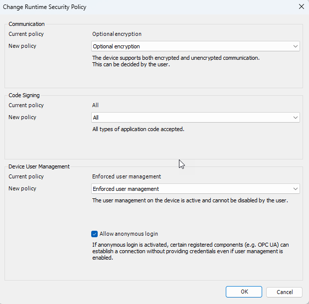
8. Log in to the device by navigating to Online > Login in CODESYS. If you are logging in for the first time, set up your user name and password. If you are an existing user, then enter your login credentials and then navigate to Device > Change Runtime Security Policy and select Allow anonymous login. Click OK.
Configure and Connect to the OPC UA Server in Simulink
Configure Simulink to connect to the CODESYS OPC UA server. Depending on whether you are doing an independent co-simulation or synchronized co-simulation, open the plc_cosim_rt or plc_cosim_sync Simulink model files.
To configure the server, open the
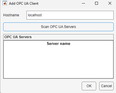
TwoDOFPIDControlsubsystem, double-click the OPC UA Read or OPC UA Write block, and select Configure servers. In the OPC Configuration window, select Add Server > Add.In the Add OPC UA Client pop-up window, enter the name of the machine with the OPC UA server. Enter localhost if the machine is the local machine. Click Scan OPC UA Servers > OK.

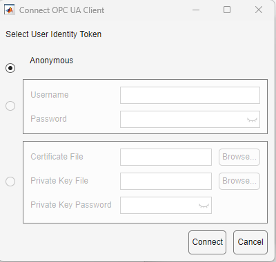
3. Select the name of your local OPC UA server machine and click OK. Next, select the server and click Connect. Select Anonymous and click Connect.

4. Add signals to the OPC UA Write and OPC UA Read blocks. To add signals, double-click the blocks, select Add, and then, in the Browse OPC UA Server Namespace window navigate to Objects > Device Set > CODESYS Control Win V3 x64 > Resources > Application > Programs > PLC_PRG, select the signals to add, and click the Add Node button.
In the
plc_cosim_rtmodel, addrtandyto the OPC UA Write block, andutto the OPC UA Read block. Ensure that the CODESYS SoftPLC is running theplc_cosim_rtproject.In the
plc_cosim_syncmodel, addrt,y, andtestCycleNumto the OPC UA Write block, andut,previousCycleNum, andtestCycleNumto the OPC UA Read block. Ensure that the CODESYS SoftPLC is running theplc_cosim_syncproject.
Simulate the Model
Next run the model. The process you follow depends on whether you run an independent or synchronized co-simulation.
Perform Independent Co-Simulation
Open the
plc_cosim_rtCODESYS project file. Click Build > Build to compile the project.Start the CODESYS SoftPLC from the Windows system tray and then log in to the device by clicking Online > Login. To run the program, click Debug > Start.
Open the
plc_cosim_rtSimulink model and connect to the OPC UA server by clicking Model Settings > OPC Configuration. Select your OPC UA server and click Connect. Select Anonymous and click Connect.Right-click the
TwoDOFPIDControlsubsystem block, and click the Block Parameters button . Set the Sample Time to
 0.1.In the Simulation tab, click Run > Simulation Pacing. Click Run to start the simulation.
Open the CODESYS IDE. In the right navigation window double-click PLC_PRG and observe the variable values changing.
After the Simulink model simulation ends, in CODESYS, click Debug > Stop. In Simulink, in the Simulation tab, in the Review Results section, click Data Inspector. Select r(t) and y(t) to observe the co-simulation results.

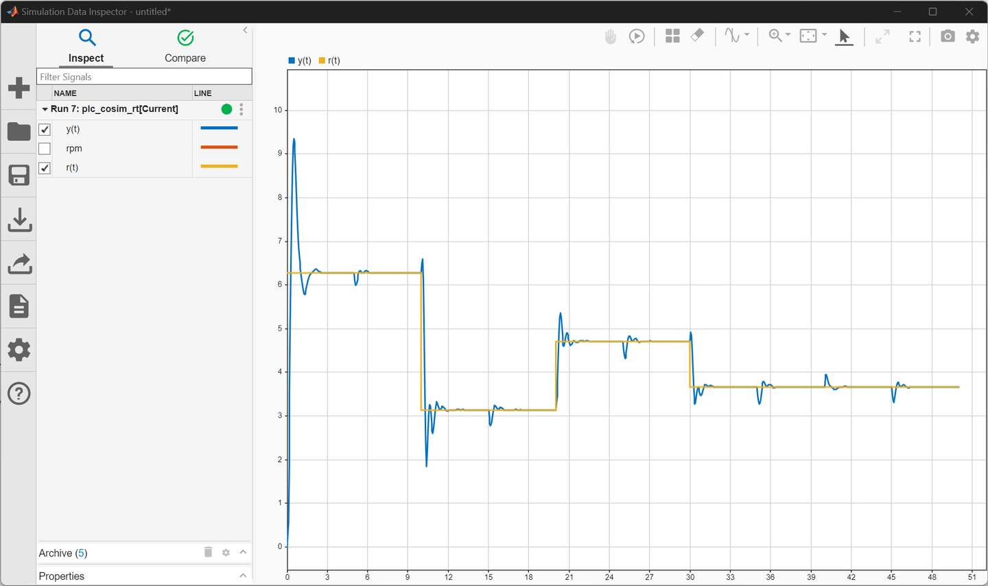
Change the TwoDOFPIDControl subsystem block Sample Time parameter to 0.05 and re-run the co-simulation steps. This image shows the co-simulation results. The lower sample time reduces the amount of lost data. Observe the smaller fluctuations in the output signal y(t).
Perform Synchronized Co-Simulation
Open the
plc_cosim_syncCODESYS project file. Click Build > Build to compile the project.Start the CODESYS SoftPLC from the Windows system tray, and log in to the device by clicking Online > Login. To run the program, click Debug > Start.
Open the
plc_cosim_syncSimulink model and connect to the OPC UA server by clicking Model Settings > OPC Configuration. Select your OPC UA server and click Connect. Select Anonymous and click Connect.Right-click the
TwoDOFPIDControlsubsystem block, and click the Block Parameters button . Set the Sample Time to
 0.1.Click Run to start the simulation.
Open the CODESYS IDE. In the right navigation window double-click PLC_PRG and observe the variable values changing.
After the Simulink model simulation ends, in CODESYS, click Debug > Stop. In Simulink, in the Simulation tab, in the Review Results section, click Data Inspector. Select r(t) and y(t) to observe the co-simulation results.
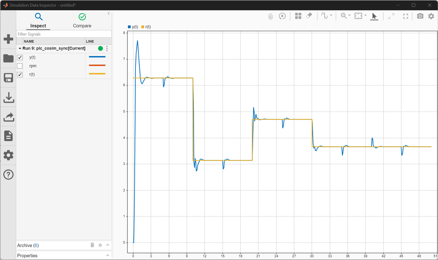
This example explains how to run the models in both independent and synchronized co-simulation mode.
See Also
OPC UA Read (Industrial Communication Toolbox) | OPC UA Write (Industrial Communication Toolbox)