Phase Current Extractor for Single Shunt FOC
Libraries:
Motor Control Blockset /
Controls /
Math Transforms
Description
The Phase Current Extractor for Single Shunt FOC block transforms the DC shunt currents, measured at the rising or falling edges of each phase's PWM pulses, into phase currents for the Single-Shunt Field Oriented Control (FOC) algorithm.
The block accepts three DC shunt measured currents as muxed input, and Sector information as integer value in the range 1 to 6.
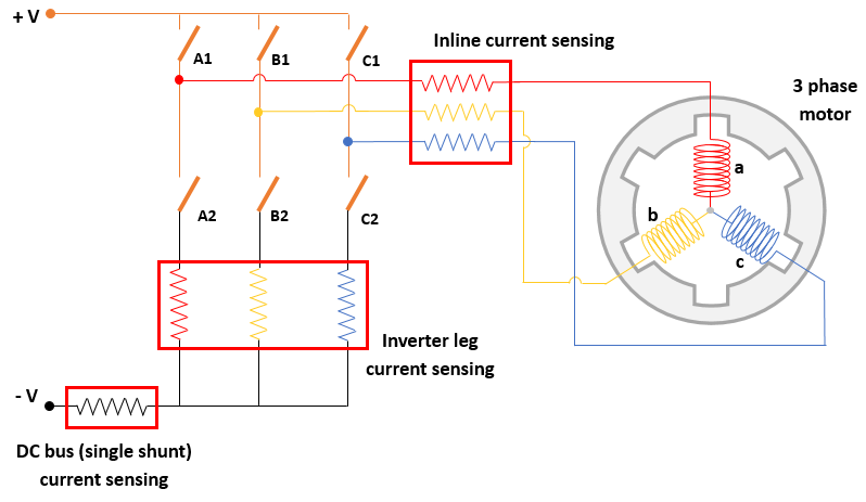
DC Bus Current Sensing
The FOC current controller uses the computed rotor position as well as measured motor currents to compute the three-phase voltages required for the motor to follow a given reference speed. The controller converts these three-phase voltages into pulse width modulation (PWM) duty cycles that operate the six inverter switches.
To generate PWM duty cycles, the current controller uses a triangular carrier waveform with a specific sampling time and generates three pulse trains that operate the inverter switches as shown in the following figure.
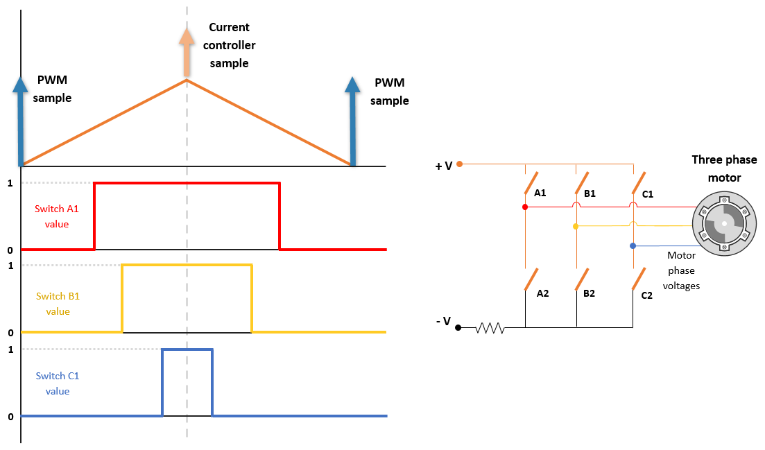
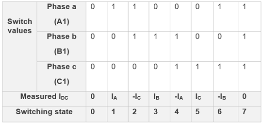
The controller operates the inverter in a complementary mode. The pulse that controls the lower transistor in an inverter leg is always opposite to the one controlling the upper transistor. Therefore, the upper-transistors of a three-phase inverter can have eight switching states (for space vector modulation PWM) described in the following table.

By operating the switches, the PWM pulses energize the three motor phases
appropriately to generate the three-phase voltages. Based on the sequence of duty pulse
duration of three motor phases, you can define six sectors. For example, the following
figure shows a sector (phase a duty duration > phase b duty duration > phase c duty duration). It shows how during a PWM
cycle, these three duties for the three motor phases, switch ON the three inverter leg
switches for different durations.
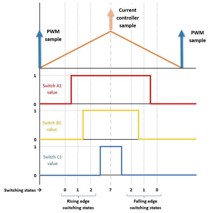
In the preceding example of PWM cycle, the three inverter leg switches show the following states.

For switching state 1 in the above figure, the switches operate as following:
Switch A1 is ON
Switch B1 is OFF
Switch C1 is OFF
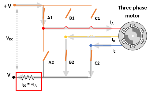
The DC bus or single shunt current measurement method only measures the current in
the DC shunt. From the preceding figure, you can infer that the DC shunt current is
equal to +Ia during this switching state. Similarly, for switching
state 2, the switches operate as following:
Switch A1 is ON
Switch B1 is ON
Switch C1 is OFF
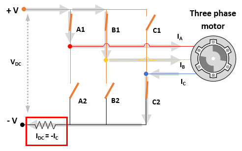
From the preceding figure, you can infer that the DC shunt current is equal to
-Ic during this switching state.
Therefore, for this PWM cycle, by measuring DC shunt current during two relevant
switching states (state 1 and 2), you can determine currents for two motor phases (in
this example, you determined Ia and
Ic). Because the example assumes a
balanced system, the algorithm computes the third phase current mathematically for each
PWM cycle.
Ib = -
(Ia +
Ic)
Similarly, other sectors have a different sequence of switching states. You can
determine the motor phase currents from the measured
IDC value using the following table.
Examples
Sensorless Field-Oriented Control of PMSM Using DC Shunt Current Sensing
Implement sensorless field-oriented control (FOC) using only a single DC bus-based current measurement to run a permanent magnet synchronous motor (PMSM).
Ports
Input
Output
Parameters
Extended Capabilities
Version History
Introduced in R2026a