Main Content

Dead-Time Compensator

Overcome dead-time effect by modifying reference voltages

Since R2024a

Libraries:
Motor Control Blockset / Signal Management
Motor Control Blockset HDL Support / Signal Management

Description

The Dead-Time Compensator block compensates for the inverter dead-time. Use this block to compensate for the dead-time effect of a three-phase inverter.

Three-phase inverters used in motor drive applications are nonlinear in nature. Dead time in an inverter (that is added to avoid short circuit in the inverter legs) contributes significantly to this nonlinearity. Even though dead time ensures safe operation of the inverter, it can adversely affect the performance of the inverter. This causes the inverter output voltage waveform to deviate from its originally expected form.

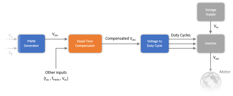
The block accepts three-phase reference voltages, measured motor currents, PWM frequency, and inverter DC voltage as inputs. It provides a three-phase voltage output that compensates for the dead-time effect of the inverter. The compensation helps reduce the noise or ripple in motor torque or currents, and therefore, improves the motor drive performance.

The following image shows the block position inside a motor control algorithm.
Ports

Input

expand all

Three-phase reference voltages (in volts).

Data Types: single | double | fixed point

Measured values of phase-a and phase-b currents of the motor (in amperes).

Data Types: single | double | fixed point

Frequency (in hertz) of the carrier wave used to perform pulse-width modulation.

Data Types: single | double | fixed point

DC voltage supply of the inverter (in volts).

Data Types: single | double | fixed point

Signal that enables block outputs:

  • 1 — Enable compensation (block outputs compensated voltages).

  • 0 — Disable compensation (block outputs input voltages).

Dependencies

To enable this port, select the Show enable port parameter.

Data Types: single | double | fixed point

Output

expand all

Motor three-phase voltages (in volts) that is compensated for inverter dead-time effect.

Data Types: single | double | fixed point

Parameters

expand all

Dead time in Inverter switches (in seconds).

Select this parameter to enable hysteresis algorithm near the region of zero-crossing of the input motor phase currents.

The block detects motor current polarity to determine voltage compensation. Using a hysteresis band near zero-crossing of currents aids in better detection of current polarity when motor currents are noisy.

Hysteresis band, h, for the current controller. The switch-on point is h and the switch-off point is -h.

Dependencies

To enable this parameter, select Enable hysteresis for currents near zero-crossing.

Number of motor current inputs. You can select one of the following options:

  • Two currents (Ia,Ib)

  • Three currents (Ia,Ib,Ic)

Inputs

Select this parameter to show the input port Enable.

Extended Capabilities

C/C++ Code Generation
Generate C and C++ code using Simulink® Coder™.

Fixed-Point Conversion
Design and simulate fixed-point systems using Fixed-Point Designer™.

Version History

Introduced in R2024a