Commutation of SRM Using Sensor Feedback
This example implements a commutation system to control the speed of a three-phase 12/8 switched reluctance motor (SRM).
It uses the switching sequences generated by the SRM Commutation block to control switch the motor phases on and off, and therefore, run the motor while controlling the motor speed. For more details about this block, see SRM Commutation.
The example uses the following values to generate a switching (or commutation) sequence for each phase available in the motor.
Electrical position signals with respect to a phase of SRM.
Position range for all phases during which they should be activated (also known as dwell angle).
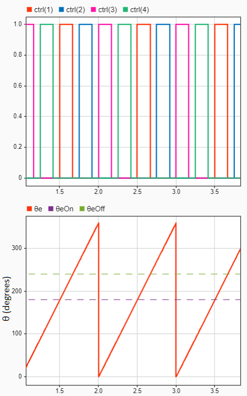
You can use each switching sequence (for example, ctr(1) signal in the following image, which forms a pulse train) to control (turn on or off) the corresponding motor phase. Each pulse in a switching sequence represents the activation period of the phase, which is defined by turn-on ( ) and turn-off (
 ) angles as shown in this diagram:
The commutation system needs real-time motor position feedback, which it obtains from a quadrature encoder sensor.
The example utilizes the Mechanical to Electrical Position block, which uses the mechanical position feedback and the number of rotor poles available in the SRM to compute the motor electrical position. It computes the electrical position with respect to each phase (Theta_e), which lies between 0 and 2π radians (0 and 360 degrees or 0 and 1 per unit).
The example uses this feedback along with the commutation logic to drive and control the speed of the rotor.
You can configure the example to use either per-unit and SI unit computation. When the controller uses per-unit computation, the example supports both fixed-point and floating-point data types. However, in the SI unit computation, the example supports only the floating-point data type.
Model
The example includes the mcb_srm_spdctrl_f28379d model.
You can use these models for both simulation and code generation.

For details about the supported hardware configuration, see Required Hardware in the Generate Code and Deploy Model to Target Hardware section.
Required MathWorks Products
To simulate model:
Motor Control Blockset™
Simscape™ Electrical™
To generate code and deploy model:
Motor Control Blockset™
Fixed-Point Designer™ (only needed for optimized code generation)
Embedded Coder®
C2000™ Microcontroller Blockset
Prerequisites
Obtain the SRM parameters. The example uses default SRM parameters in the Simulink model that you can replace with values from the motor datasheet or other sources.
Update SRM parameters in the model initialization script associated with the Simulink model. For instructions, see Estimate Control Gains and Tune Control Parameters
In addition, update the following parameters in the model initialization script:
PWM_frequency — Enter the switching frequency of the PWM. You might need to tune the controller gains again if you change this value.
datatype
- single — Use this value for floating-point code generation. In this mode, the example supports both per-unit and SI unit computation.
- fixdt(1,32,17) — Use this value for fixed-point code generation. In this mode, the example supports only per-unit computation.
controllerunit
▫ 1 — Use this value to enable SI unit computation.
▫ 0 — Use this value to enable per-unit computation.
Kp and Ki — Enter the PI controller gains. The example does not automatically compute these values. Fine tune these gains according to the hardware setup.
thetaON — Enter the motor phase turn-on electrical position at which the switching sequence turns from 0 to 1 and energizes the corresponding phase.
thetaOFF — Enter the motor phase turn-off electrical position at which the switching sequence turns from 1 to 0 and de-energizes the corresponding phase.
Simulate Model
This example supports simulation. Follow these steps to simulate the model.
1. Open the target model included with this example.
2. Click Run on the Simulation tab to simulate the model.
3. Click Data Inspector on the Simulation tab to view and analyze the simulation results.
Generate Code and Deploy Model to Target Hardware
This section shows you how to generate code and run the control algorithm on the target hardware.
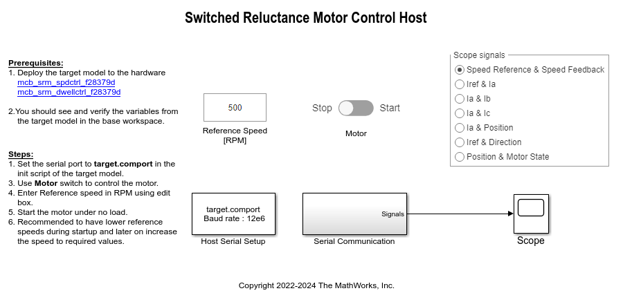
This example uses a host and a target model. The host model is a user interface to the controller hardware board. You can run the host model on the host computer. To use the host model, first deploy the target model to the controller hardware board. The host model uses serial communication to command the target Simulink model and run the motor in closed-loop control.
Required Hardware
The example supports the following hardware configuration. You can also use the target model name to open the model from the MATLAB® command prompt.
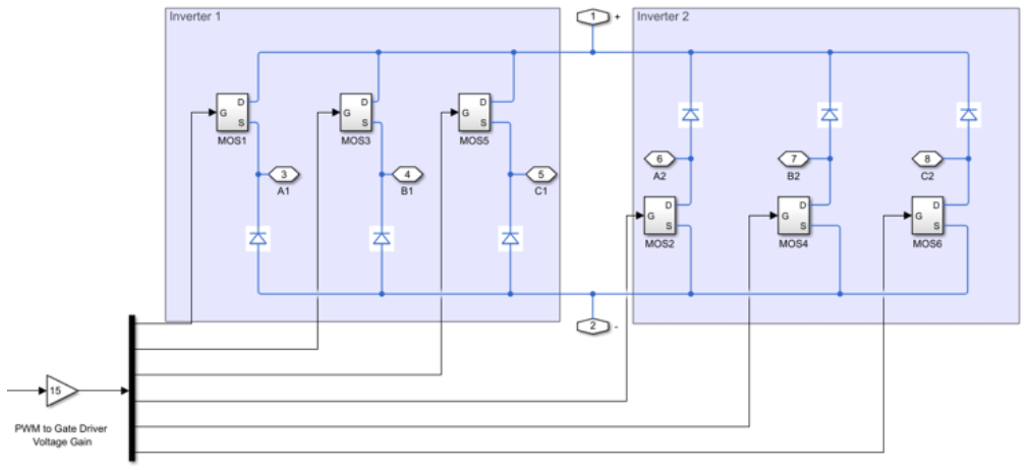
LAUNCHXL-F28379D controller + 2 BOOSTXL-DRV8305 inverters:
mcb_srm_spdctrl_f28379d
The example algorithm uses the ADC current sensors available in the inverter boards to measure the three-phase motor currents that it needs to control SRM.
Hardware Connections
The example requires two BOOSTXL-DRV8305 inverters connected in the following configuration.
For more information about hardware connections for SRM, see Instructions for Switched Reluctance Motor (SRM) Setup.
Generate Code and Run Model on Target Hardware
1. Simulate the target model and observe the simulation results.
2. Complete the hardware connections.
3. The model computes the ADC (or current) offset values by default. To disable this functionality, update the value 0 to the variable inverter.ADCOffsetCalibEnable in the model initialization script.
Alternatively, you can compute the ADC offset values and update them manually in the model initialization script.
4. Open the target model. If you want to change the default hardware configuration settings of the model, see Model Configuration Parameters.
5. Load a sample program to CPU2 of the LAUNCHXL-F28379D controller to ensure that CPU2 is not mistakenly configured to use the board peripherals intended for CPU1. For example, load the program that operates the CPU2 blue LED by using the GPIO31 port (c28379D_cpu2_blink.slx). For more information about the sample program or model, see the Task 2 - Create, Configure and Run the Model for TI Delfino F28379D LaunchPad (Dual Core) section in Getting Started with Texas Instruments C2000 Microcontroller Blockset (C2000 Microcontroller Blockset).
6. Click Build, Deploy & Start on the Hardware tab to deploy the target model to the hardware.
7. Observe and verify the variables populated by the target model in the base workspace.
8. Click the mcb_srm_spdctrl_host.slx host model> hyperlink in the target model to open the associated host model.
For details about serial communication between the host and target models, see Host-Target Communication.
9. In the model initialization script associated with the target model, specify the communication port using the variable target.comport. The example uses this variable to update the Port parameter of the Host Serial Setup, Host Serial Receive, and Host Serial Transmit blocks available in the host model.
10. Update the reference speed value in the Reference Speed (RPM) field in the host model. We recommend that you enter lower speeds when the motor is starting up and then gradually increase the speed.
11. In the host model, select the debug signals that you want to monitor.
12. Click Run on the Simulation tab to run the host model.
13. Ensure that the motor is in no-load condition. Change the position of the Motor switch to Start, to start running the motor.
If the motor does not align or if it fails to start running in open-loop mode, increase the values of the start-up parameters listed in the Motor Start Up Parameters section of the model initialization script.
14. The example performs the following procedures:
Calibrates the quadrature encoder sensor (which includes alignment of the rotor with stator phase A).
Runs SRM in closed loop according to Reference Speed (RPM).
15. Observe the debug signals received from the target in the Scope available in the host model.