Field-Oriented Control
This is the third workflow that runs a three-phase permanent magnet synchronous motor (PMSM) using closed-loop field-oriented control (FOC). For more details about FOC, see Field-Oriented Control. The workflow uses a host and a target model. The host model is a user interface to the controller hardware board. You can run the host model on the host computer. Before you run the host model on the host computer, build and deploy the target model algorithm (integrated with the hardware drivers) to the controller hardware board. The host model uses serial communication to command the target model algorithm and run the motor.
Expand the foc_qep folder to access these files.
current_control_algorithm.slx(target model for current controller)speed_control_algorithm.slx(target model for speed controller)foc_qep_sim.slx(target model for simulation)foc_qep_data.m(model initialization script associated with the target models)foc_qep_host.slx(host model)
Before using this workflow, complete Open-Loop Control and ADC Offset Calibration and Quadrature Encoder Offset Calibration to compute the ADC and
position sensor offsets. Update the offsets in these variables available in the model
initialization script foc_qep_data.m:
inverter.CtSensAOffset and inverter.CtSensBOffset variables (ADC offsets for Ia and Ib current sensors)
pmsm.PositionOffset (position offset for quadrature encoder sensor)
Simulate Model
This example supports simulation. Follow these steps to simulate the model.
Open the model
foc_qep_sim.slx.To simulate the model, click Run on the Simulation tab.
To view and analyze the simulation results, click Data Inspector on the Simulation tab.
Generate Code For Control Algorithm Using Embedded Coder
After you open the MATLAB® project, double-click the
current_control_algorithm.slxfile in thefoc_qepfolder.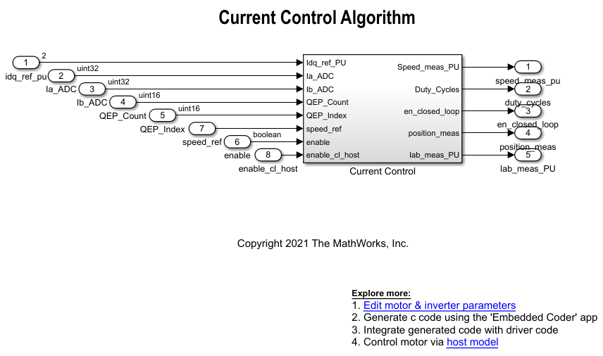
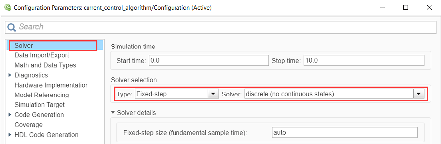
Select Modeling > Model Settings > Model Settings to open the Configuration Parameters dialog box.
In the Solver Selection area of the Solver tab, update the Type and Solver fields.
In the Hardware Implementation tab of the Configuration Parameters dialog box, configure the parameters according to your hardware.

Obtain the motor and inverter parameters. The target model uses default motor parameters that you can replace with values from either the motor datasheet or other sources.
However, you can use your motor control hardware to estimate the parameters for the motor that you want to use by using the Motor Control Blockset parameter estimation tool. For instructions, see Estimate PMSM Parameters Using Custom Hardware. The parameter estimation tool updates the motorParam variable (in the MATLAB workspace) with the estimated motor parameters.
Update the motor and inverter parameters. If you obtain the motor parameters from the datasheet or from other sources, update the motor and inverter parameters in the model initialization script (
foc_qep_data.m) associated with the Simulink® model. For instructions, see Estimate Control Gains and Tune Control Parameters.If you use the parameter estimation tool, you can update the inverter parameters, but do not update the motor parameters in the model initialization script. The script automatically extracts the motor parameters from the updated motorParam workspace variable.
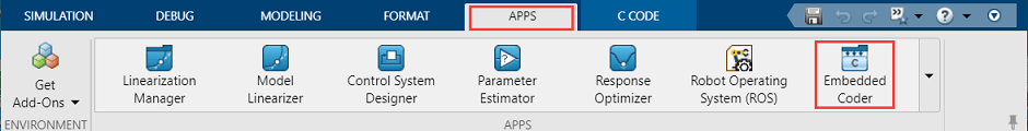
In the Simulink toolstrip of the target model, select Apps > Embedded Coder to open the Embedded Coder application.
In the Simulink toolstrip, select C Code > Code Interface > Default Code Mappings to open the Code Mappings - C dialog box.

In the Code Mappings - C dialog box, open the Functions tab.
For a listed C function, click the hyperlink under the Function Preview column to open the Configure C Initialize Function Interface dialog box.

Use the Configure C Initialize Function Interface dialog box to configure the interface and arguments of the C function.
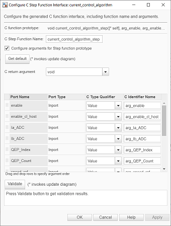
Click Apply and OK to complete configuring the C function.
Repeat steps 10 to 12 for all the listed functions.
In the Simulink toolstrip of the target model, select C Code > Generate Code > Build to build the model and generate a
.cfile for the target model for current controller.
This image shows an example of a C function available in the generated current controller code.
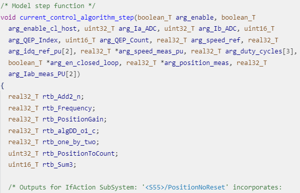
Note
The generated C function uses the interface that you configured in step 11.
For details about the per-unit system used in the algorithm, see Per-Unit System.
Repeat steps 1 to 14 for the target model for speed controller
(speed_control_algorithm.slx) to generate the speed
controller code.
Obtain C Code For Hardware Drivers
You can use the code generation software supported by the hardware manufacturer to
generate the code for the hardware drivers. For example, for the reference
STM32F302R8 controller and X-NUCLEO-IHM07M1 inverter, you can use the STM32CubeMX STM32Cube initialization code generator software to
configure the hardware peripherals and generate C code for the hardware drivers. The
example also includes the FOC_QEP.ioc file (created by
STM32CubeMX software) containing the hardware initialization data for the reference
hardware.
Alternatively, you can also use a manually written driver code.
Integrate Control Algorithm Code With Driver Code
Integrate the code for the speed and current controllers.
Call the control algorithm functions from the driver code using the configured control algorithm function parameters. This image shows a call to the speed control algorithm C function.
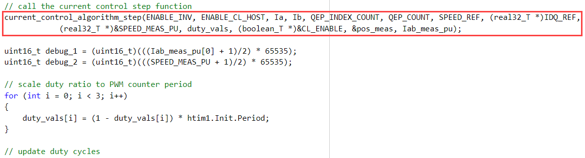
Use the return value from the function call to complete integrating the driver with the controller algorithm.
For details about the code structure and program control flow used by the Motor Control Blockset™ examples, see Program Control Flow of Motor Control Blockset Examples.
View the integrated sample code main.c available in the
foc_qep\STM32Code folder as a reference.
Deploy Integrated Code to Hardware
Complete the hardware connections.
Use the code generation and deployment software supported by the hardware manufacturer to compile, build, and generate a binary (for example
.HEX) file from the integrated code. Use the software to flash the binary file to the target hardware.For example, for the reference STM32F302R8 controller and X-NUCLEO-IHM07M1 inverter, use the STM32CubeMX STM32Cube initialization code generator to generate and flash the binary file.
Control Motor Using Host Simulink Model
Follow these steps to determine the offset of the quadrature encoder sensor attached to a three-phase PMSM:
Click the host model hyperlink in the target model to open the associated host model. You can also double-click the
foc_qep_host.slxfile in thefoc_qepfolder.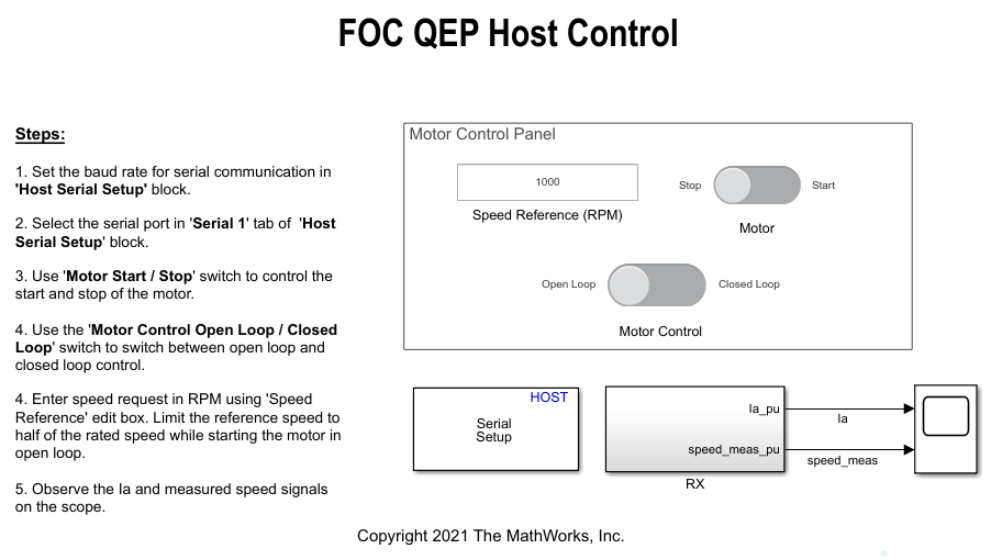
In the Serial 1 tab of the block parameters dialog boxes for the Host Serial Setup, Host Serial Receive, and Host Serial Transmit blocks, select a Port name and enter a Baud rate for serial communication.
For details about the serial communication between the host and target models, see Host-Target Communication.
Click Run on the Simulation tab to run the host model.
Ensure that the current position of Motor Control slider switch is Open Loop. Turn the Motor Start / Stop slider switch to the Start position to start running the motor using open-loop control.
Before entering closed-loop control, enter the reference speed for the motor in the Speed Reference (RPM) field. It is recommended that you set the speed to a value that is approximately half the rated speed of the motor.
Turn the Motor Control slider switch to the Closed Loop position to start running the motor using closed-loop field-oriented control.
Observe the Ia and speed signals in the time scope.