Get Started with Arduino Explorer
R2026bThis example shows how to use the Arduino® Explorer app to connect to an Arduino board and monitor sensor inputs and control peripherals based on temperature readings.
In this example, the Arduino board is connected to a temperature sensor, an LED, and a servo motor. The Arduino Explorer app provides a unified interface to read temperature sensor values and control the LED and servo motor.
After generating MATLAB® code from the app, the generated script is modified so that the LED turns on or off and the servo motor position changes based on a specified temperature threshold.
Video Walkthrough
For a walkthrough of the example, play the video below.
Open Arduino Explorer App
To open the app, on the MATLAB® Toolstrip, click the Apps tab. In the Test and Measurement section, click Arduino Explorer. 
Alternatively, you can open the app by typing the following command in the command window:
arduinoExplorer;
After launching the app, select the device card corresponding to the Arduino board you want to work with. If the app does not detect your device automatically and it does not appear in the All Hardware section, use one of the configuration cards on the top to manually add your device based on connection type. For more information, see Set Up and Connect to Arduino and Arduino-compatible Boards Using Arduino Explorer.
You can also customize some of the user interface elements in the app. For more information, see Customizable Views in the App.
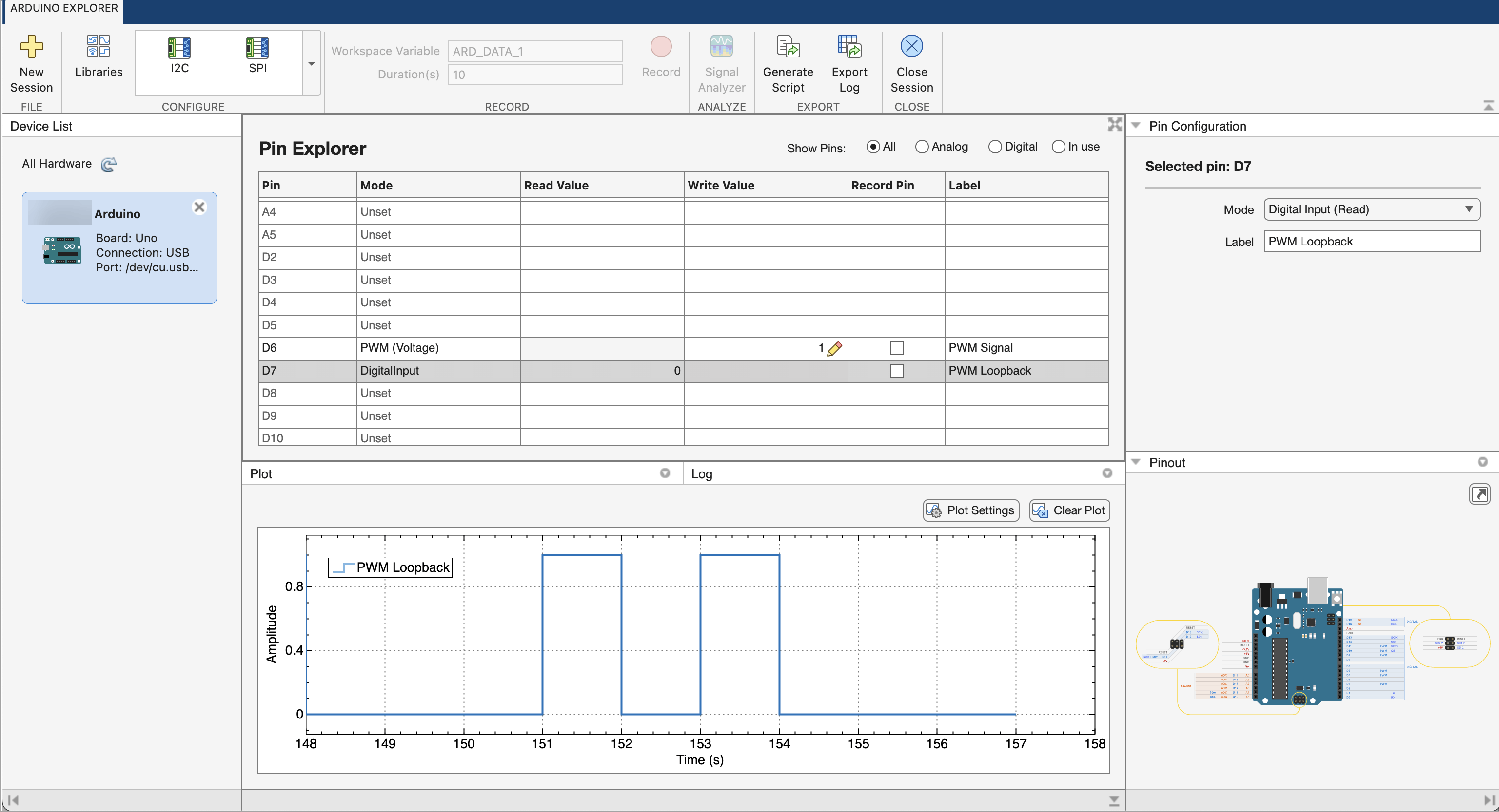
The app includes a:
Toolstrip — The Arduino Explorer toolstrip provides controls to configure communication interfaces, record and analyze data, generate MATLAB scripts, export logs, and manage hardware sessions.
Device List — Displays the available hardware connections and lets you select the Arduino board to work with.
Pin Explorer Panel — Provides a table‑based view to configure pins, read inputs, write outputs, and select pins for recording. It also lets you filter Analog, Digital, and In use pins.
Pin Configuration Panel — Displays the options you can use to configure the selected pin, including Mode and Label.
Plot Tab — Displays live plots of signal values from input pins. The plot updates in real time as the values at the pin change.
Log Tab — Provides a table with data communication details such as time stamp, type of operation, data value, value of decoded data, size of data, and the data type.
Pinout Panel — Shows the pinout diagram of the connected board.
Required Hardware
To run this example, you must have the following hardware:
Arduino® board
Analog output temperature sensor
Servo motor
LED
Resistor (220 Ω to 330 Ω)
Hardware Setup
Make sure that you wire your pins as follows:
Temperature Sensor
Temperature Sensor Pin | Arduino Pin |
VCC / + | 5V |
GND / − | GND |
OUT | A0 |
Servo motor
Servo motor | Arduino Pin |
Power | 5V |
Ground | GND |
Signal | D3 |
LED
LED | Arduino Pin |
Anode (longer leg) | D2 (through a resistor) |
Cathode (shorter leg) | GND |
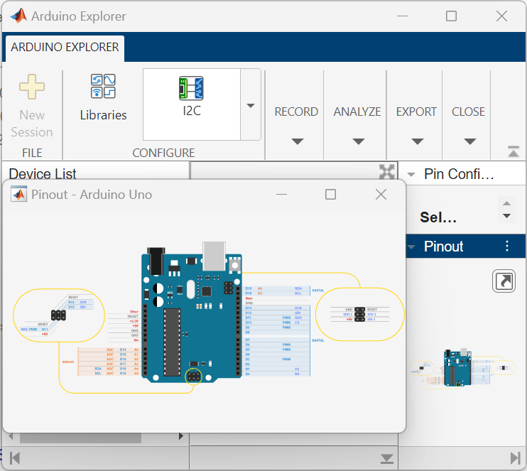
To view the pinout diagram of the board, use the Pinout panel. The pinout diagram helps you identify the Arduino pins to connect the peripherals to the board.
Configure Arduino Board and Peripherals
To read data from the Arduino board and communicate with peripherals, you must configure the relevant pins in the Pin Explorer pane. The app provides a pinout diagram to help you identify which pins to connect and configure.
Configure Temperature Sensor
Set up analog pin A0 to receive input from the temperature sensor. In the Pin Explorer, select the row for A0. In the Pin Configuration panel, set the Mode to Analog Input (Read), and name the acquired signal by setting the Label to TempData. An analog temperature sensor outputs a continuous voltage that varies proportionally with temperature. The Analog Input (Read) mode enables the Arduino to sample this voltage through its analog-to-digital converter, returning values between 0 V and 5 V that you can then map to a temperature range using the sensor datasheet.
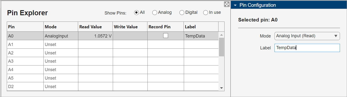
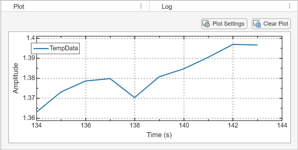
The app automatically starts reading data and plots the values in the Plot tab. You may turn off plotting by deselecting the pin in the Plot tab.
Configure LED and Servo Motor
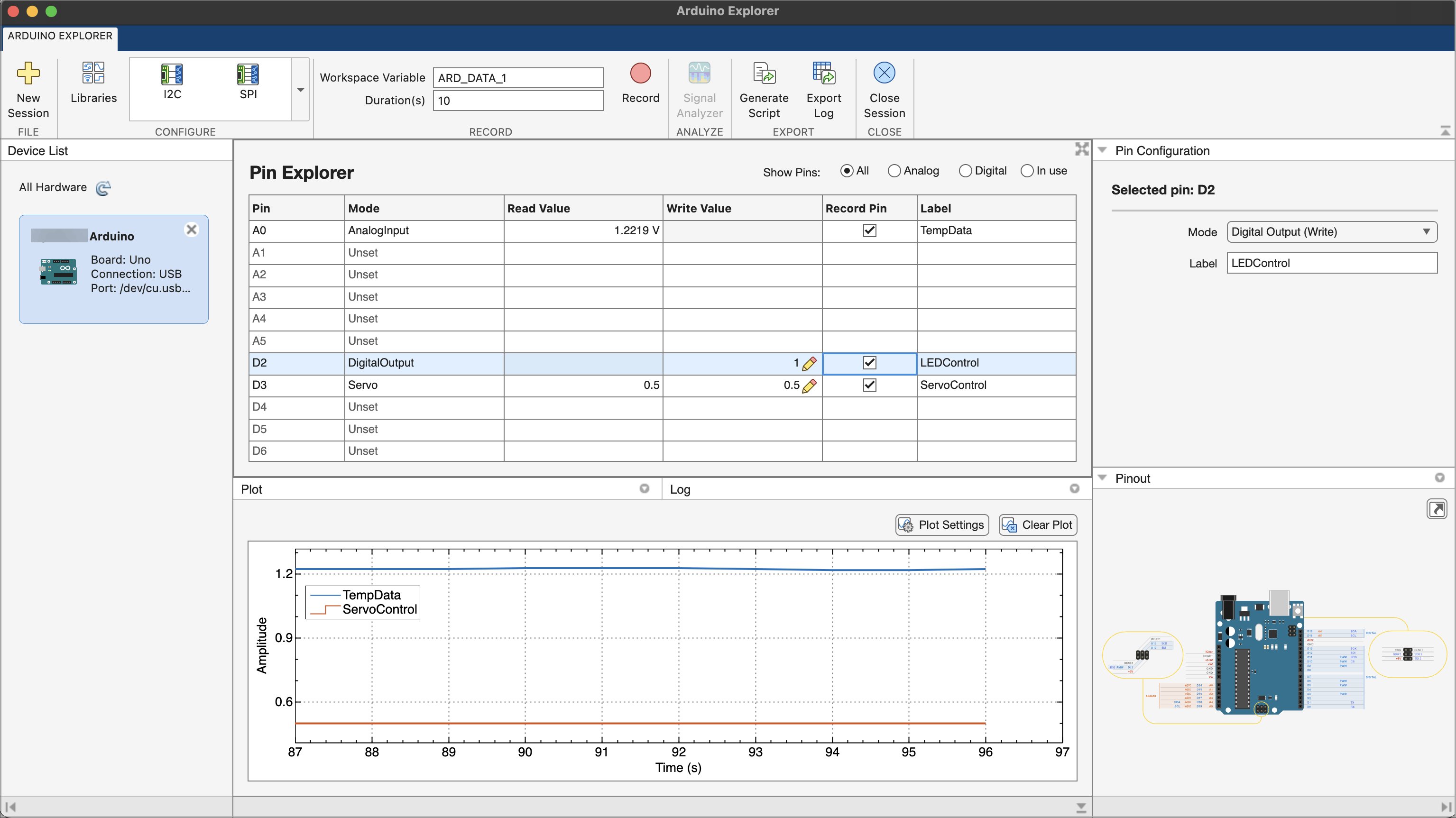
Configure the digital pins connected to the LED and servo motor. In the Pin Explorer, select the row for D2. In the Pin Configuration panel, set the Mode to Digital Output (Write) and set the Label to LEDControl. The Digital Output (Write) mode lets the Arduino set the pin to high (1) or low (0), which switches the LED on or off.
Now configure the pin connected to the servo motor. In the Pin Explorer, select the row for D3. Set the Mode to Servo and set the Label to ServoMotor.
Monitor and Control Peripherals
You can view the incoming values for read pins in the Read Value column of the Pin Explorer pane. Pin A0 shows the input voltage from the temperature sensor. The voltage value displayed for pin A0 corresponds to the temperature reading from the sensor.
Pin D3 shows the current angle of the servo motor shaft (normalized).
You can control peripherals from the app too, using the Write Value column to specify values to write to the pins. To turn on the LED, write 1 to digital pin D2. To rotate the servo motor, write the desired position value to D3.
Record and Visualize Data
To record data from the pins, in the Pin Explorer, select Record Pin for the desired pins, then in the toolstrip, click Record. The app records data for the specified duration and writes it to a workspace variable. If you have the Signal Processing Toolbox, you can also visualize and analyze the recorded data using the Signal Analyzer app.
Generate and Update MATLAB Code
Your Arduino board and peripherals are now configured to communicate with MATLAB. To add further control logic and processing, you can generate a MATLAB script that contains commands to create an Arduino connection, configure the pins, and read and write data. To generate this MATLAB script, click Generate Script.

You can use this script as a starting point for your own control logic and data processing.
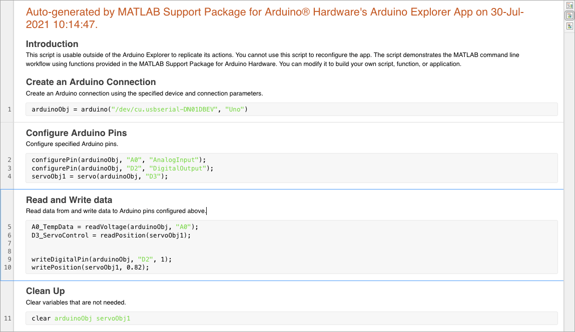
You can add your own logic to the code to control the peripherals based on sensor readings.
% Set threshold voltage value
thresholdVoltage = 1.5;

% Set duration to monitor
duration = 60;
tObj = tic;

% Monitor temperature for the specified duration
while (toc(tObj) <= duration)

    A0_TempData = readVoltage(arduinoObj, "A0");
    D3_ServoControl = readPosition(servoObj1);

    % Add custom logic to control the Servo and LED based on voltage read from
    % temperature sensor
    if A0_TempData > thresholdVoltage
        writeDigitalPin(arduinoObj, "D2", 1);
        writePosition(servoObj1, 0.82);
    else
        writeDigitalPin(arduinoObj, "D2", 0);
        writePosition(servoObj1, 0);
    end
end
This script continuously reads the temperature sensor voltage and the current servo motor position for 60 seconds. When the voltage exceeds a specified threshold, thresholdVoltage, the LED turns on and the servo motor rotates to a defined position. Otherwise, the LED turns off and the servo returns to its default position. You can also download the updated code temperatureControl.m attached with this example.

