CoMP Dynamic Point Selection with Multiple CSI Processes
This example shows how multiple Channel State Information (CSI) processes provide the network with feedback for Coordinated Multipoint (CoMP) operation. In this example User Equipment (UE) data is transmitted from one of two cooperating eNodeB as part of a Dynamic Point Selection (DPS) scheme. The transmission decision is based on Channel Quality Indicator (CQI) reports from the UE.
Introduction
Coordinated multipoint (CoMP) is a term used to describe schemes in which a group of base stations dynamically cooperate to mitigate interference, or even turn this interference into a useful signal. The group of coordinating base stations is termed the cooperating set. CoMP in LTE Release 11 is designed to be able to take advantage of low latency and high capacity backhaul between base stations within a cooperating set. Therefore data for a User Equipment (UE) may be available at one or more cooperating base stations.
There are three categories of downlink CoMP:
In Coordinated Scheduling and Beamforming (CS/CB), UE data is only available at a single base station within the coordinating set, therefore the PDSCH is transmitted from a single base station. Scheduling and link adaptation are coordinated using information from other base stations within the cooperating set. Other cooperating base stations can also coordinate their scheduling and beamforming decisions to mitigate interference.
In Dynamic Point Selection (DPS), UE data is available at multiple base stations within the coordinating set but data is only transmitted from one base station at a time. The base station transmitting to the UE, named the transmission point (TP), can be changed subframe-to-subframe, to provide the best transmission for a UE with varying channel conditions. This scenario is most likely at a cell edge, where long term channel characteristics favor the serving base station, but short term characteristics may favor other cooperating base stations.
In Joint Transmission (JT), UE data is transmitted from multiple base stations simultaneously. This can be coherent or non-coherent. Coherent JT jointly precodes transmissions from multiple TPs to allow the receiver to achieve coherent combining of the transmission. In non-coherent JT, each TP precodes the transmission independently, therefore only a power gain is available to the receiver.
The network uses Channel State Information (CSI), reported by the UE, or inferred from TDD uplink transmissions, to make CoMP transmission decisions. The UE feeds back multiple reports, each of which correspond to different hypotheses regarding the transmission decisions of cooperating base stations. To provide a report, a UE is configured with a CSI process. A CSI process consists of a CSI Reference Signal (CSI-RS) resource, a CSI interference Measurement resource (CSI-IM) and a reporting mechanism. For CSI reporting, the network can configure a UE with up to four CSI processes. For each CSI process the UE reports calculated CSI indicators as requested by the network:
Channel Quality Indicator (CQI)
Rank Indicator (RI)
Precoder Matrix Indicator (PMI)
For more information about CQI/RI/PMI reporting see the examples Reporting of Rank Indicator (RI) Conformance Test and Reporting of Channel Quality Indicator (CQI) Conformance Test.
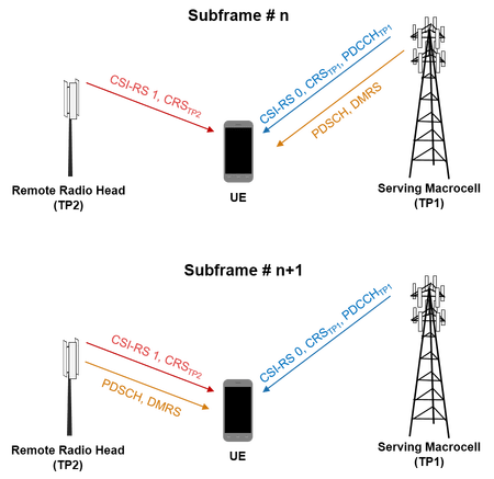
This example shows a simple DPS scenario for PDSCH transmission to a UE. The cooperating set contains two transmission points, TP1 and TP2, each of which is capable of transmitting the PDSCH to the UE. TP1 is the serving cell for the UE. The network selects the PDSCH transmission point and the modulation and coding scheme using the CQI reported by the UE. The following diagram shows the principle of DPS operation in this example. Both transmission points transmit a CSI-RS and cell-specific reference signal (CRS). The serving cell also transmits downlink control information for the UE in the PDCCH. The PDSCH transmission point can change subframe-to-subframe to take advantage of instantaneous channel conditions. In the diagram the PDSCH transmission point changes from TP1 in subframe n to TP2 in subframe n+1.
In this example the CSI processes and transmission points are configured as required by the conformance test "CQI Reporting requirement with multiple CSI processes" in TS36.101 Section 9.3.6.1 [ 1 ]. This example differs from this conformance test by selecting one of two possible PDSCH transmission points based on the highest reported wideband CQI from either transmission point. In this conformance test the PDSCH transmission point is fixed. Additionally no CQI reporting delay is implemented.
Simulation Controls
In this example the PDSCH transmission point can be either dynamically selected or fixed to the serving cell, TP1, using the parameter dpsOperation. Use this parameter to explore the impact of DPS on throughput.
dpsOperation = true; % Enable DPS {true,false}
totSubframes = 150;  % Number of subframes to simulate
Transmission Point Configurations
Two transmission points are defined and configured as per TS36.101 Table 9.3.6.1-1 [ 1 ]: TP1 is a macro cell (the serving cell) and TP2 is a cooperating base station such as a remote radio head. A structure array enb contains the parameters for both transmission points.
% Transmission point 1 cell-wide settings
enb = struct;
enb.NDLRB = 50;
enb.CellRefP = 2;
enb.DuplexMode = 'FDD';
enb.CFI = 3;
enb.CyclicPrefix = 'Normal';
enb.NFrame = 0;
enb.NCellID = 0;

% PDSCH configuration for transmission mode 10 (TM10)
enb.PDSCH.TxScheme = 'Port7-14';
enb.PDSCH.NLayers = 1;
enb.PDSCH.RNTI = 1;
enb.PDSCH.NSCID = 0;
enb.PDSCH.Modulation = {'16QAM'};
enb.PDSCH.Rho = 0;
enb.PDSCH.RV = 0;
enb.PDSCH.NTurboDecIts = 5;
enb.PDSCH.PRBSet = (0:enb.NDLRB-1).';
enb.PDSCH.NTxAnts = 4;
enb.PDSCH.W = lteCSICodebook(enb.PDSCH.NLayers,enb.PDSCH.NTxAnts,0).';
enb.PDSCH.AltCodebook4Tx = 'Off';
enb.PDSCH.CSI = 'On';
The configuration for TP2 is based on TP1. Different cell-specific settings are configured as required.
enb = repmat(enb,2,1);
enb(2).NCellID = 6;
enb(2).PDSCH.NTxAnts = 2;
enb(2).PDSCH.W = lteCSICodebook(enb(2).PDSCH.NLayers,enb(2).PDSCH.NTxAnts,0).';
Transmission Hypothesis, CSI Resources and CSI Processes
When the two coordinating transmission points use DPS, the PDSCH can be transmitted from either TP1 or TP2. When the PDSCH is transmitted by one transmission point to a UE, for example TP1, there are two transmission options for the other transmission point, TP2. The first option is to serve other UEs using the same resources thereby interfering with the PDSCH transmission from TP1. The second option is to mute transmission in these resources thereby not interfering with the PDSCH transmission from TP1. These options are grouped into transmission hypotheses. In this example four transmission hypotheses are tested by the network:
               TP1 Hypothesis       TP2 Hypothesis
------------------------------------------------------
Hypothesis 0:  Transmitting PDSCH   Muting
Hypothesis 1:  Muting               Transmitting PDSCH
Hypothesis 2:  Transmitting PDSCH   Interfering
Hypothesis 3:  Interfering          Transmitting PDSCH
Although four hypotheses are tested in this example, PDSCH transmissions made to the UE are only consistent with hypotheses 2 or 3.
To provide the network with CSI for these transmission hypotheses, two CSI-RS resources and three CSI-IM resources are configured at the UE. CSI processes use these resources to report CSI for each hypothesis.
In the following sections the resources and CSI processes are configured to test these four transmission hypotheses.
CSI-RS Resources
A unique CSI-RS is transmitted by each cooperating base station. The UE is configured with two CSI-RS resources to provide channel quality estimates, one for each transmission point:
CSI-RS #0: Transmission from TP1
CSI-RS #1: Transmission from TP2
Each CSI-RS is defined by a configuration, a period and a CSI-RS scrambling identity. The number of CSI reference ports is the number of transmit antennas. For this simulation the periods of CSI-RS and CSI-IM resources must be the same. These are parameterized by SimCSIPeriod.
SimCSIPeriod = [5 1]; % [Tcsi-rs Dcsi-rs]

% CSI-RS resource: {CSI-RS #0, CSI-RS #1}
SimCSIRS.CSIRSConfig = [0 5];                       % CSI-RS configuration
SimCSIRS.CSIRSPeriod = {SimCSIPeriod,SimCSIPeriod}; % CSI-RS period
SimCSIRS.NCSIID = [10 16];                          % CSI-RS scrambling identity
SimCSIRS.CSIRefP = [enb(1).PDSCH.NTxAnts enb(2).PDSCH.NTxAnts];
CSI-IM Resources
CSI-IM resources describe a set of Resource Elements (REs) over which the average power is measured by the UE. These measurements are used to estimate the interference for CSI calculations. Three CSI-IM are required to measure interference when the TPs are transmitting:
CSI-IM #0: Measure background noise when both TPs are muted
CSI-IM #1: Measure TP2 interference
CSI-IM #2: Measure TP1 interference
Each CSI-IM is defined by a configuration and a period. Note the configurations differ from the CSI-RS configurations but the periods are the same.
% CSI-IM resource: {CSI-IM #0, CSI-IM #1, CSI-IM #2}
SimCSIIM.ZeroPowerCSIRSConfig = [2 6 1];
SimCSIIM.ZeroPowerCSIRSPeriod = {SimCSIPeriod,SimCSIPeriod,SimCSIPeriod};
CSI Processes
Four processes are configured to test the four transmission hypotheses. These use the CSI-RS and CSI-IM resources described above:
            TP1 Hypothesis      TP2 Hypothesis      CSI-RS     CSI-IM
------------------------------------------------------------------------
Process 0:  Transmitting PDSCH  Muting              CSI-RS #0  CSI-IM #0
Process 1:  Muting              Transmitting PDSCH  CSI-RS #1  CSI-IM #0
Process 2:  Transmitting PDSCH  Interfering         CSI-RS #0  CSI-IM #1
Process 3:  Interfering         Transmitting PDSCH  CSI-RS #1  CSI-IM #2
A process is defined by a CSI-RS resource, a CSI-IM resource and a reporting mode. The CSI reporting mode, PMI reporting mode and codebook subset restriction for each process are configured as per TS36.101 Table 9.3.6.1-1 [ 1 ]. The codebook subset restriction for each process restricts PMI selection to a single PMI therefore PMI and RI reporting is not required.
% {CSI Process #0, CSI Process #1, CSI Process #2, CSI Process #3}
SimCSIProcess.CSIRSResource  = [1 2 1 2]; % CSI-RS resources index (1 based)
SimCSIProcess.CSIIMResource  = [1 1 2 3]; % CSI-IM resources index (1 based)
SimCSIProcess.CSIMode        = {'PUCCH 1-1','PUSCH 3-1','PUSCH 3-1','PUSCH 3-1'}; % CSI reporting modes
SimCSIProcess.PMIMode        = {'Wideband' ,'Wideband' ,'Wideband','Wideband'};   % PMI reporting modes
SimCSIProcess.CodebookSubset = {'0x0000000000000001','000001','0x0000000000000001','000001'}; % Codebook subset restrictions
In this simulation only two of the four hypotheses are implemented by the network; PDSCH transmission from either TP1 or TP2 with the other TP interfering. Therefore only the feedback from CSI processes 2 and 3 is used for the transmission decision.
Fading Channel and SNR Configuration
The SNR for each transmission to the UE is defined in TS36.101 Table 9.3.6.1-1 [ 1 ]. The noise power is defined using Noc.
snrTP = [11 8]; % SNR of received transmission from TP1 and TP2
Noc = -98;      % dBm/15kHz average power spectral density
A fading channel is configured between TP1 and the UE, and TP2 and the UE. The structure array chcfg parameterizes the channels from TP1 and TP2.
% Channel between TP1 and UE
ofdmInfo = lteOFDMInfo(enb(1));
chcfg = struct;
chcfg.DelayProfile = 'EPA';
chcfg.NRxAnts = 2;
chcfg.DopplerFreq = 5;
chcfg.MIMOCorrelation = 'Low';
chcfg.SamplingRate = ofdmInfo.SamplingRate;
chcfg.InitPhase = 'Random';
chcfg.ModelType = 'GMEDS';
chcfg.NTerms = 16;
chcfg.NormalizeTxAnts = 'On';
chcfg.NormalizePathGains = 'On';
chcfg.Seed = 1;

% Channel between TP2 and UE
chcfg = repmat(chcfg,2,1);
chcfg(2).Seed = 2;

% Calculate the size of the received waveform
rxWaveformSize = [chcfg(1).SamplingRate*1e-3+15 chcfg(1).NRxAnts];
Channel Estimation Configuration
Two reference signals must be used by the UE: the CSI-RS and DM-RS. Two separate channel estimation configurations are required to estimate each reference signal. Here cubic interpolation will be used with an averaging window of 1-by-2 REs. This configures the channel estimator to use a special mode which ensures the ability to despread and orthogonalize the CSI-RS and DMRS transmissions.
% CSI-RS estimation
ceccsi.FreqWindow = 1;
ceccsi.TimeWindow = 2;
ceccsi.InterpType = 'cubic';
ceccsi.PilotAverage = 'UserDefined';
ceccsi.InterpWinSize = 1;
ceccsi.InterpWindow = 'Causal';
ceccsi.Reference = 'CSIRS';

% DM-RS estimation
cecdmrs = ceccsi;
cecdmrs.Reference = 'DMRS';
Transmission Point Parameterization for CSI Estimation and Reporting
In this section the transmission points are parameterized from the configured CSI-RS resources and CSI-IM resources for CSI-RS generation and PDSCH mapping. The appropriate parameters are set in the configuration structure array enb.
CSI-RS Resources
Both transmission points are parameterized with all CSI-RS configured at the UE.
% Set TP1 and TP2 CSI-RS configuration
for enbIdx = 1:2
    enb(enbIdx).CSIRefP = SimCSIRS.CSIRefP;
    enb(enbIdx).CSIRSConfig = SimCSIRS.CSIRSConfig;
    enb(enbIdx).CSIRSPeriod = SimCSIRS.CSIRSPeriod;
    enb(enbIdx).NCSIID = SimCSIRS.NCSIID;
end
ZP CSI-RS Resources
Zero Power (ZP) CSI-RS resources prevent the PDSCH from being mapped to a set of REs. Therefore ZP CSI-RS are used to mute REs within each TP PDSCH transmission to allow configured CSI-IM to measure the interference for different hypotheses.
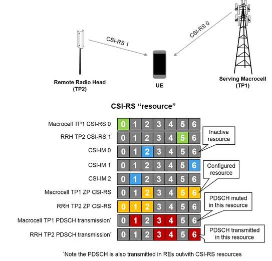
The diagram below illustrates how ZP CSI-RS are configured to allow CSI-IM resources to measure interference. CSI-IM #0 measures the noise when neither TP is transmitting in resource 2. Therefore to prevent the TPs transmitting in this resource, the ZP CSI-RS is configured in resource 2 for both TPs. This stops the PDSCH being mapped to this resource, muting the transmission. The ZP CSI-RS for each TP is also configured to map around the CSI-RS of the coordinating TP to prevent interference. CSI-IM #1 and CSI-IM #2 measure the individual interference caused by TP2 and TP1 in resources 6 and 1. Therefore the ZP CSI-RS for TP1 is configured to prevent PDSCH transmission in resource 6 to allow measurement with CSI-IM #1. The ZP CSI-RS for TP2 is configured to prevent PDSCH transmission in resource 1 to allow measurement with CSI-IM #2.
The ZP CSI-RS are configured with a 16-bit bitmap. Each bit controls whether a set of REs should be muted (1) or unmuted (0). For each transmission point, a ZP CSI-RS configuration is created from the required CSI-IM configurations and the CSI-RS configuration used by the coordinating transmission point.
% ZP CSI-RS resource for TP1
zp1 = '0000000000000000';                          % Assume all CSI configurations unmuted
zp1(SimCSIIM.ZeroPowerCSIRSConfig([1 2])+1) = '1'; % Mute CSI-IM #0,1 (background & TP2 interference)
zp1(SimCSIRS.CSIRSConfig(2)+1) = '1';              % Mute CSI-RS #1 (TP2 transmission)

% Add ZP CSI-RS resource to TP1 parameters
enb(1).ZeroPowerCSIRSConfig = zp1;
enb(1).ZeroPowerCSIRSPeriod = SimCSIPeriod;

% ZP CSI-RS resource for TP2
zp2 = '0000000000000000';                          % Assume all CSI configurations unmuted
zp2(SimCSIIM.ZeroPowerCSIRSConfig([1 3])+1) = '1'; % Mute CSI-IM #0,2 (background & TP1 interference)
zp2(SimCSIRS.CSIRSConfig(1)+1) = '1';              % Mute CSI-RS #0 (TP1 transmission)

% Add ZP CSI-RS resource to TP2 parameters
enb(2).ZeroPowerCSIRSConfig = zp2;
enb(2).ZeroPowerCSIRSPeriod = SimCSIPeriod;
UE Parameterization for CSI Estimation and Reporting
In this example the CSI-RS, CSI-IM and CSI processes are represented at the UE as structure arrays. Each element of the structure array configures a single resource or process. This section creates these structure arrays from the configured CSI-RS resources and CSI-IM resources.
The structure array csirs contains the CSI-RS resource parameterization. This is based on the parameters of the serving cell but the CSI-RS parameters are configured to use the appropriate resource given in the simulation settings.
numCSIRS = numel(SimCSIRS.CSIRSConfig);
csirs = repmat(enb(1),numCSIRS,1);
for idx = 1:numCSIRS
    csirs(idx).CSIRefP = SimCSIRS.CSIRefP(idx);
    csirs(idx).CSIRSConfig = SimCSIRS.CSIRSConfig(idx);
    csirs(idx).CSIRSPeriod = SimCSIRS.CSIRSPeriod{idx};
    csirs(idx).NCSIID = SimCSIRS.NCSIID(idx);
end
The structure array csiim contains the CSI-IM resource parameterization. This is based on the parameters of the serving cell but the CSI-IM parameters are configured to use the appropriate resource give in the simulation settings. As a CSI-IM resource is a ZP CSI-RS configuration the CSIRSPeriod parameter is set to 'Off' so only ZP CSI-RS REs are used to measure interference.
numCSIIM = numel(SimCSIIM.ZeroPowerCSIRSConfig);
csiim = repmat(enb(1),numCSIIM,1);
for idx = 1:numCSIIM
    csiim(idx).ZeroPowerCSIRSConfig = SimCSIIM.ZeroPowerCSIRSConfig(idx);
    csiim(idx).ZeroPowerCSIRSPeriod = SimCSIIM.ZeroPowerCSIRSPeriod{idx};
    csiim(idx).CSIRSPeriod = 'Off';
end
The structure array process contains the CSI process parameterization. This is based on the parameters of the serving cell. The parameters CSIRSIdx and CSIIMIdx are used to index the CSI-RS and CSI-IM resources for calculating CSI. The reporting modes are configured for each process from the simulation settings. The CQI reported by the UE for each CSI process is selected using the estimated Signal to Interference plus Noise Ratio (SINR). The lowest SINRs recommended to achieve 90% throughput for each CQI index in this scenario are defined by the vector SINRs. This vector is used to parameterize the CQI selection for each CSI process.
SINRs = [1.3 1.3 2.3 3.7 5 6.8 9.2 10.9 13 14.8 17.1 18.9 21 23.9 24.3];
numCSIProcesses = numel(SimCSIProcess.CSIRSResource);
process = repmat(enb(1),numCSIProcesses,1);
for idx = 1:numCSIProcesses
    % Index CSI-RS and CSI-IM resources used by the process
    process(idx).CSIRSIdx = SimCSIProcess.CSIRSResource(idx);
    process(idx).CSIIMIdx = SimCSIProcess.CSIIMResource(idx);

    % Reporting configuration
    process(idx).PDSCH.CSIMode = SimCSIProcess.CSIMode{idx};
    process(idx).PDSCH.PMIMode = SimCSIProcess.PMIMode{idx};
    process(idx).PDSCH.CodebookSubset = SimCSIProcess.CodebookSubset{idx};
    process(idx).PDSCH.SINRs90pc = SINRs;

    % CSI-RS configuration for CSI estimation
    process(idx).CSIRefP = SimCSIRS.CSIRefP(process(idx).CSIRSIdx);
    process(idx).CSIRSConfig = SimCSIRS.CSIRSConfig(process(idx).CSIRSIdx);
    process(idx).CSIRSPeriod = SimCSIRS.CSIRSPeriod(process(idx).CSIRSIdx);
    process(idx).NCSIID = SimCSIRS.NCSIID(process(idx).CSIRSIdx);
end
Simulation Setup
The required signal power to satisfy the SNR for each TP is calculated below.
% Convert to linear and Watts
nocLin = 10.^(Noc/10)*(1e-3); % linear in Watts
% Take into account number of antennas and FFT (OFDM) scaling
No = sqrt(nocLin/(2*double(ofdmInfo.Nfft)));
NocW = 10.^((Noc-30)/10); % convert to W/15kHz

% SINR = Es/Noc TS 36.101 Sec. 8.1.1
NocTot = NocW; % W/15kHz
snrLin = 10.^(snrTP/10);
Es = snrLin*NocTot; % W/15kHz

% Amplitude scaling factors
K = sqrt(Es);
Variables required for the simulation are initialized in this section.
% Set the random number seed
rng('default');

% Initialize containers which store the channel estimates interference
% measurements for CSI-RS and CSI-IM resources
csirshest = cell(numCSIRS,1);
csiimnest = zeros(numCSIIM,1);

% Initialize a buffer to store CQI reports for each process. Size buffer
% for subband CQI reporting.
numCSIReports = ceil(totSubframes/SimCSIPeriod(1));
pmiInfo = ltePMIInfo(process(1),setfield(process(1).PDSCH,'PMIMode','Subband')); %#ok<SFLD>
cqiBuffer = ones(numCSIReports,pmiInfo.NSubbands+1,numCSIProcesses);

% Initialize buffers to store the CRC, BER and TP selected
crcBuffer = cell(totSubframes,1);
berBuffer =  zeros(totSubframes,2);
tpBuffer = zeros(totSubframes,1);

csiReportIdx = 1; % Index of CSI report
lastOffset = 0;   % Initialize overall frame timing offset
frameOffset = 0;  % Initialize frame timing offset
Simulation Loop
The simulation is run subframe-by-subframe. For each subframe the following steps are carried out:
A time domain waveform
rxWaveformis initialized with noise. The received waveform from TP1 and TP2 will be added to this.The PDSCH TP is selected using the wideband CQI reported by the UE.
For each TP in turn a subframe is generated containing the relevant synchronizing and reference signals and TM10 OCNG.
The PDSCH for the UE is generated from either TP1 or TP2 in a single subband.
The two subframes are OFDM modulated, passed through a fading channel, and combined.
The received waveform at the UE is synchronized and OFDM demodulated.
The configured CSI-RS and CSI-IM measurements are performed by the UE
A CSI report is generated using the CSI-RS and CSI-IM resources for configured CSI processes.
The PDSCH is demodulated.
for nsf = 0:totSubframes-1
    % Initialize UE receive waveform with noise
    rxWaveform = No*complex(randn(rxWaveformSize),randn(rxWaveformSize));

    % Select PDSCH TP based on the highest reported wideband CQI
    bufferIdx = mod(csiReportIdx-2,numCSIReports)+1; % Buffered CQI to use
    if dpsOperation
        widebandCQI = permute(cqiBuffer(:,1,:),[1 3 2]);
        if (widebandCQI(bufferIdx,3)>=widebandCQI(bufferIdx,4))
            pdschTransmissionPoint = 1; % TP1
        else
            pdschTransmissionPoint = 2; % TP2
        end
    else
        pdschTransmissionPoint = 1; %#ok<UNRCH> % TP1
    end

    % Generate TP1 and TP2 transmissions.
    % Each transmission contains cell-specific reference signal,
    % synchronizing signals, CSI-RS and TM10 OCNG. One transmission
    % contains the PDSCH for the UE.
    for enbIdx = 1:2
        % Update subframe number for each transmission
        enb(enbIdx).NSubframe = nsf;

        % Turn off the CSI resource not transmitted by this TP
        tpenb = enb(enbIdx);
        tpenb.CSIRSPeriod{mod(enbIdx,2)+1} = 'Off';

        % Blank subframe; CRS, PSS and SSS
        sf = lteResourceGrid(tpenb,tpenb.PDSCH.NTxAnts);
        crsInd = lteCellRSIndices(tpenb); % Cell-specific reference signal
        sf(crsInd) = lteCellRS(tpenb);
        pssInd = ltePSSIndices(tpenb);    % Primary synchronizing signal
        sf(pssInd) = ltePSS(tpenb);
        sssInd = lteSSSIndices(tpenb);    % Secondary synchronizing signal
        sf(sssInd) = lteSSS(tpenb);

        % CSI-RS resource
        csitp = tpenb;
        csitp.ZeroPowerCSIRSPeriod = 'Off';
        csiInd = lteCSIRSIndices(csitp);
        sf(csiInd) = lteCSIRS(csitp);

        % TM10 OCNG transmitted apart from subframes containing PSS/SSS/PBCH
        if isempty(pssInd)
            tpenb.PDSCH.RNTI = 0;

            % Add OCNG at DMRS locations
            oncngInd = lteDMRSIndices(tpenb,tpenb.PDSCH);
            ocngSym = lteDMRS(tpenb,tpenb.PDSCH);
            sf(oncngInd) = ocngSym;

            % Add OCNG for PDSCH symbols
            [oncngInd,ocngInfo] = ltePDSCHIndices(tpenb,tpenb.PDSCH,tpenb.PDSCH.PRBSet);
            ocngSym = ltePDSCH(tpenb,tpenb.PDSCH,randi([0 1],ocngInfo.G,1));
            sf(oncngInd) = ocngSym;
        end

        % PDSCH and DMRS Transmission to UE from either TP1 or TP2.
        % The transport block size and modulation scheme for transmission
        % are selected using the reported CQI for the appropriate CSI
        % process. The PDSCH must be mapped around the ZP CSI-RS configured
        % for the UE and the ZP CSI-RS of the TP. Only transmit PDSCH for
        % subframes not containing CSI resources or PSS/SSS as per TS36.101
        % Table 9.3.6.1-1.
        if ~isempty(pssInd)||~isempty(csiInd)
            tbs = 0; % Transport block size is 0 as no PDSCH transmitted
        elseif (pdschTransmissionPoint==enbIdx)
            tpBuffer(nsf+1) = pdschTransmissionPoint;
            % Get relevant configuration for transmission point and CQI to
            % use.
            txenb = enb(enbIdx);
            cqi = cqiBuffer(bufferIdx,:,enbIdx+2);

            % Select subband for PDSCH transmission.
            % The PDSCH is transmitted in the highest differential CQI
            % subband. Subbands less than full size are excluded.
            partialSubband = (pmiInfo.k*pmiInfo.NSubbands>txenb.NDLRB);
            [~,idx] = max(cqi(2:(end-partialSubband))); % Maximum differential
            sbCandidates = find(cqi(2:(end-partialSubband))==cqi(idx+1));
            sb = sbCandidates(randi([1 numel(sbCandidates)],1,1));
            cqi = cqi(1)+cqi(1+sb); % Calculate SB PMI from wideband and differential
            txenb.PDSCH.PRBSet = ((sb-1)*pmiInfo.k+(0:(pmiInfo.k-1))).'; % PRB allocation for subband

            % Select MCS according to CQI using TS36.101 Table A.4-1 CSI
            % RMC RC.12 FDD (MCS.13), which defines the relationship
            % between CQI indices and MCS indices
            imcsTable = [-1 0 0 1 3 5 7 10 12 14 17 19 21 22 24 25];
            imcs = imcsTable(cqi+1);

            % Determine TBS and modulation order, fixed RI (1) and PMI (0).
            % Generate PDSCH for only a non-zero transport block size.
            [itbs,modulation] = lteMCS(imcs);
            tbs = double(lteTBS(size(txenb.PDSCH.PRBSet,1),itbs));
            if any(tbs)
                if ~iscell(modulation)
                    modulation = {modulation};
                end
                txenb.PDSCH.NLayers = 1;
                txenb.PDSCH.Modulation = modulation;
                txenb.PDSCH.W = lteCSICodebook(txenb.PDSCH.NLayers,txenb.PDSCH.NTxAnts,0).';

                % PDSCH mapping
                [pdschInd,pdschInfo] = ltePDSCHIndices(txenb,txenb.PDSCH,txenb.PDSCH.PRBSet);

                % Generate DL-SCH data
                txtrblk = arrayfun(@(x)randi([0 1],x,1),tbs,'UniformOutput',false);
                cw = lteDLSCH(txenb,txenb.PDSCH,pdschInfo.G,txtrblk);

                % Generate PDSCH symbols with cell identity of serving cell
                % for correct scrambling
                txenb.NCellID = enb(1).NCellID;
                pdschSym = ltePDSCH(txenb,txenb.PDSCH,cw);

                % Create UE specific DMRS configuration to allow for
                % scrambling code to change depending on transmission point
                txenb.NCellID = enb(1).NCellID;
                if pdschTransmissionPoint == 2
                    txenb.NCellID = enb(2).NCellID;
                end
                dmrsInd = lteDMRSIndices(txenb,txenb.PDSCH);
                dmrsSym = lteDMRS(txenb,txenb.PDSCH);

                % Map PDSCH and DMRS
                sf(pdschInd) = pdschSym;
                sf(dmrsInd) = dmrsSym;
            end
        end

        % OFDM modulate, pass through a fading channel, scale for SNR and
        % add to existing receive waveform
        txWaveform = lteOFDMModulate(tpenb,sf);
        txWaveform = [txWaveform; zeros(15,size(txWaveform,2))]; %#ok<AGROW>
        chcfg(enbIdx).InitTime = nsf/1e3;
        rxWaveform = rxWaveform + K(enbIdx)*lteFadingChannel(chcfg(enbIdx),txWaveform);
    end

    % Receiver Synchronization and OFDM demodulation
    % Synchronize using the PSS/SSS of the serving cell (TP1) and OFDM
    % demodulate
    if ~isempty(pssInd)
        frameOffset = lteDLFrameOffset(enb(1),rxWaveform);
        if (frameOffset > 25)
            frameOffset = lastOffset;
        end
        lastOffset = frameOffset;
    end
    rxWaveform = rxWaveform(1+frameOffset:end,:);
    rxsf = lteOFDMDemodulate(enb(1),rxWaveform);

    % Calculate CSI-RS Estimates
    % Generate channel estimates for CSI-RS resources configured at the UE.
    for idx = 1:numCSIRS
        % Calculate channel estimate
        csirs(idx).NSubframe = nsf;
        csirshest{idx} = lteDLChannelEstimate(csirs(idx),csirs(idx).PDSCH,ceccsi,rxsf);
    end

    % Calculate interference using CSI-IM
    % For each CSI-IM resource calculate the energy in resource elements.
    % This is the noise+interference estimate.
    for idx = 1:numCSIIM
        % Calculate noise and interference estimate
        csiim(idx).NSubframe = nsf;
        imIndices = lteCSIRSIndices(csiim(idx));
        imSym = lteExtractResources(imIndices,rxsf);
        csiimnest(idx) = mean(abs(imSym(:)).^2);
    end

    % CSI Process Reporting
    % When estimated CSI resource elements are not zero calculate CSI
    if ~isempty(csiInd)
        % For each CSI process calculate CSI feedback
        for idx = 1:numCSIProcesses
            % Update subframe number
            process(idx).NSubframe = nsf;

            % Extract CSI-RS estimate and CSI-IM estimate for process
            hest = csirshest{process(idx).CSIRSIdx};
            nest = csiimnest(process(idx).CSIIMIdx);

            % Calculate CQI/PMI/RI, condition CQI on PMI/RI selection
            [ri,PMISet] = lteRISelect(process(idx),process(idx).PDSCH,hest,nest);
            process(idx).PDSCH.PMISet = PMISet;
            process(idx).PDSCH.NLayers = ri;
            process(idx).PDSCH.NCodewords = min(ri,2);
            [cqi,sinrs] = lteCQISelect(process(idx),process(idx).PDSCH,hest,nest);
            cqiBuffer(csiReportIdx,1:numel(cqi),idx) = cqi;
        end

        % New CSI report
        csiReportIdx = csiReportIdx+1;
    end

    % PDSCH Demodulation
    % If the transport block size is not 0, a PDSCH exists to decode
    if any(tbs)
        % Estimate channel using DMRS. To use the correct scrambling
        % sequence for the DMRS use the configuration for the active TP.
        [dmrshest,dmrsnest] = lteDLChannelEstimate(txenb,txenb.PDSCH,cecdmrs,rxsf);

        % Extract PDSCH symbols from received grid and channel estimate
        [sym,symhest] = lteExtractResources(pdschInd,rxsf,dmrshest);

        % Scale the received symbols by the PDSCH power factor Rho and
        % decode the PDSCH with the CellID for the serving cell
        sym = sym*(10^(-txenb.PDSCH.Rho/20));
        txenb.NCellID = enb(1).NCellID;
        [cws,recsym] = ltePDSCHDecode(txenb,txenb.PDSCH,sym,symhest,dmrsnest);
        % Scale cws by 1/K(1) to avoid numerical issues with DLSCH decoding
        cws = cellfun(@(x) x*(1/K(1)),cws,'UniformOutput',false);
        [trblk,crc] = lteDLSCHDecode(txenb,txenb.PDSCH,tbs,cws,[]);

        % Store CRC and BER
        crcBuffer{nsf+1} = double(crc);
        berBuffer(nsf+1,:) = [sum(trblk{1}~=txtrblk{1}),numel(trblk{1})];
    end
end
Conclusion and Results
The Block Error Rate (BLER) and PDSCH throughput are displayed for the simulation duration. Two figures are also created:
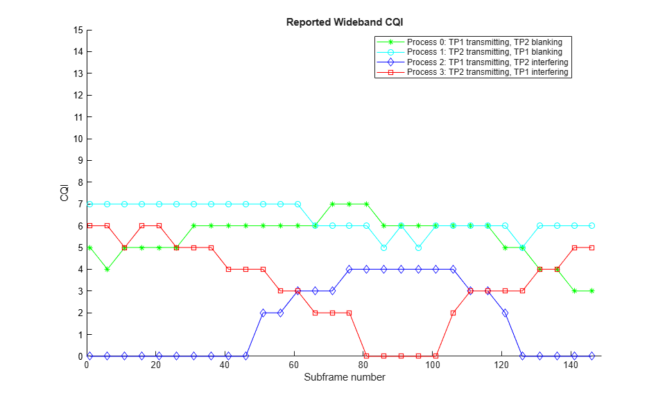
The first figure plots the reported wideband CQI for each CSI process over the duration of the simulation. The reported CQI of process 0 and process 1 show the channel conditions favor TP1 during the middle of the simulation but TP2 otherwise, as the reported CQI exceeds than of TP1. The reported CQI of processes 2 and 3 show a similar pattern, but the reported CQI is lower than for processes 0 and 1. This is because these processes assume added interference from the TPs.
The second figure plots the PDSCH transmission point selected and the reported wideband CQI of the two processes used to make the transmission point decision. This figure shows TP1 was selected for PDSCH transmission during the middle of the simulation as the reported CQI favored this transmission point.
hCoMPResults(totSubframes,SimCSIPeriod,crcBuffer,berBuffer,cqiBuffer,tpBuffer);
BLER: 0.044444 (target is 0.1)
Throughput: 266.875 kbps

This example showed how multiple CSI processes provide feedback for DPS CoMP operation. UE data was transmitted from one of two cooperating eNodeB, based on the wideband CQI reported by the UE. This examples simulated a cell-edge scenario where DPS provides a throughput gain for the UE. Try disabling DPS by setting dpsOperation = false and note the decrease in throughput.
Appendix
This example uses the following helper function:
Selected Bibliography
3GPP TS 36.101 "User Equipment (UE) radio transmission and reception"
3GPP TS 36.211 "Physical channels and modulation"
Erik Dahlman, 4G: LTE/LTE-Advanced for Mobile Broadband, Elsevier 2014
Joydeep Acharya, Heterogeneous Networks in LTE-Advanced, Wiley 2014
Select a Web Site
Choose a web site to get translated content where available and see local events and offers. Based on your location, we recommend that you select: United States.
You can also select a web site from the following list
Americas
- América Latina (Español)
- Canada (English)
- United States (English)
Europe
- Belgium (English)
- Denmark (English)
- Deutschland (Deutsch)
- España (Español)
- Finland (English)
- France (Français)
- Ireland (English)
- Italia (Italiano)
- Luxembourg (English)
- Netherlands (English)
- Norway (English)
- Österreich (Deutsch)
- Portugal (English)
- Sweden (English)
- Switzerland
- United Kingdom (English)