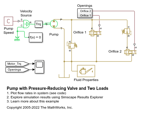
Pump with Pressure-Reducing Valve and Two Loads
This example shows a power unit consisting of a fixed-displacement pump, constant angular velocity source, pressure relief valve, pressure-reducing valve, and two variable orifices. The two variable orifices simulate fluid consumption in the main branch and in the reduced pressure branch, respectively.
Model
Simulation Results from Scopes

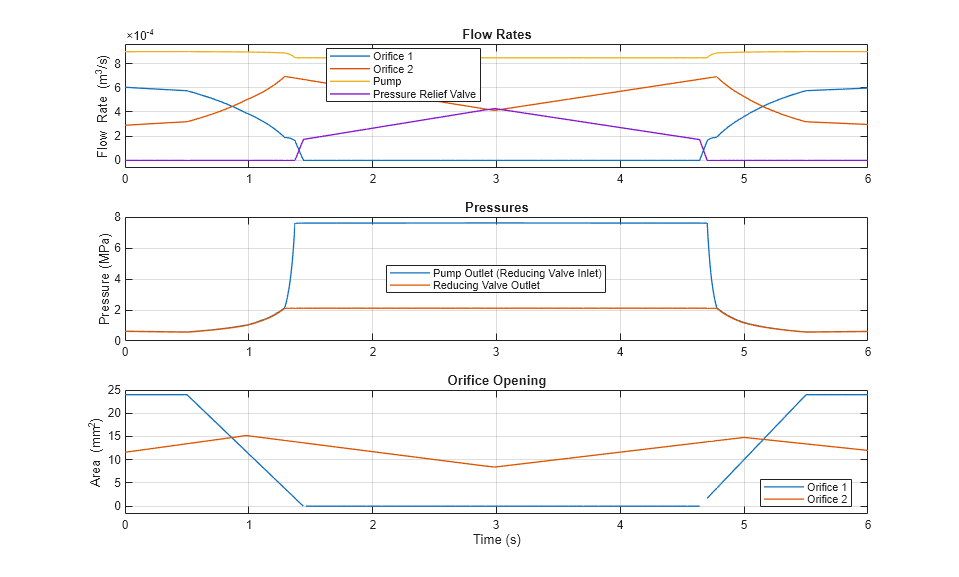
Simulation Results from Simscape Logging
These plots show how flow rates and pressures vary in the system as the orifices open and close. The simulation starts with both variable orifices open, which results in low pressure at the pump outlet and the maximum flow rate from the pump. The orifice for the main branch starts closing at 0.5 seconds and fully closes around 1.5 seconds, while the opening of the other orifice moderately varies over time. As the orifice at the main branch closes, the pump outlet pressure increases close to 7.5 MPa, which is the set pressure differential of the pressure relief valve. The increased pressure persists as the pressure relief valve diverts fluid. The pressure-reducing valve has the set pressure of 2 MPa, keeping this pressure at its outlet when the upstream pressure is greater than the set pressure.