Model a Radiator as a Heat Exchanger
This example shows how to model a radiator as a heat exchanger by using the physical measurements of the radiator, thermodynamic properties of the two fluids, and the properties of the heat transfer materials used in the radiator. The example explains how to specify the parameters of the heat exchanger, write a script that calculates the variables used in these parameters, and create a model to test the functionality of the block.
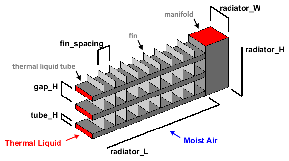
In the radiator, the thermal liquid flows through a number of rectangular tubes from left to right, and the moist air flows from front to back. Between the tubes, there are fins that the moist air contacts while flowing through.
This graphic is a corner cross-section of the radiator that shows the measurements and the direction of the fluid flow.

Measurements and Properties Given for the Radiator
| Variable Name | Measurement Description | Value | Units |
|---|---|---|---|
radiator_L | Length of the heat exchanger portion of the radiator | 0.6 | m |
radiator_W | Width of the radiator | 0.015 | m |
radiator_H | Height of radiator | 0.2 | m |
tubes_N | Number of radiator fluid tubes | 25 | N/A |
tube_H | Height of each individual fluid tube | 0.0015 | m |
fin_spacing | Distance between adjacent fins | 0.002 | m |
wall_thickness | Wall thickness of the radiator fluid tubes | 0.1 | mm |
wall_conductivity | Thermal conductivity of the fluid tube wall material | 240 | W/(m*K) |
liquid_pipe_D | Diameter of the tubes going to and from the radiator | 0.019 | m |
Model the Radiator
Because the radiator fluid is not expected to change phase, you can model it with the thermal liquid domain. Because environmental air can contain a non-negligible amount of moisture, you can model it with the moist air domain. Use the Heat Exchanger (TL-MA) block to model the radiator.
Enter sscnew('modelname','thermal_liquid') at the MATLAB command line
to open a new thermal liquid model.
Add a Heat Exchanger (TL-MA) block to this model and open it in order to specify its parameters.
Start the Script
Create a new MATLAB script and specify the measurements and properties of the heat
exchanger. Most of these values are shown in the above graphic. tubes_N
is the total number of thermal liquid tubes in the radiator.
wall_thickness is the thickness of the material of the thermal liquid
tubes. wall_conductivity is the thermal conductivity of this material.
liquid_pipe_D is the diameter of the pipe at the input and output
ports of the radiator.
radiator_L = 0.6; % [m]
radiator_W = 0.015; % [m]
radiator_H = 0.2; % [m]
tubes_N = 25;
tube_H = 0.0015; % [m]
fin_spacing = 0.002; % [m]
wall_thickness = 1e-4; % [m]
wall_conductivity = 240; % [W/(m*K)]
liquid_pipe_D = 0.019; % [m]
Set the Geometry Parameters for the Thermal Liquid
In the Thermal Liquid 1 settings:
Set the Flow geometry parameter to
Flow inside one or more tubes.Set the Number of tubes parameter to
tubes_N.Set the Total length of each tube parameter to
radiator_L. Because the thermal liquid tubes span the entire length of the radiator, this value is the full radiator length.Set the Tube cross section parameter to
Rectangular.Specify the internal width and height of the thermal liquid tubes as
tube_W_internalandtube_H_internal. In this radiator, the width of each tube is the same as the total width of the radiator. However, the thermal liquid surface area is the inner surface area of these tubes. Subtract twice the wall thickness from both the width and height of the tubes to calculate these values.tube_H_internal = tube_H - 2 * wall_thickness; % [m] tube_W_internal = radiator_W - 2 * wall_thickness; % [m]
Set the Tube width and Tube height parameters to
tube_W_internalandtube_H_internal, respectively. Set the units for both parameters tom.Set the Total fin surface area parameter to 0.
Set the Geometry Parameters for the Moist Air
In the Moist Air 2 settings:
Set the Flow geometry parameter to
Generic.Specify the distance between the adjacent thermal liquid tubes as
gap_Hand then the cross-sectional area for the moist air flow through the radiator asair_area_flow.air_area_flowparameter represents the smallest cross-sectional area that the moist air must flow through inside the heat exchanger. Because there are no particular constrictions to the moist air flow, use the total cross sectional flow area. The air flows through the gaps between the thermal liquid tubes.gap_H = (radiator_H - tubes_N * tube_H) / (tubes_N - 1); % [m] air_area_flow = (tubes_N - 1) * radiator_L * gap_H; % [m^2]
Set the Minimum free-flow area parameter to
air_area_flow.Specify the external surface area of the thermal liquid tubes as
air_area_primary. This parameter is the primary heat transfer surface area between the moist air and the heat exchanger. The value of this parameter is equal to the external surface area of the tubes that the thermal liquid is flowing through. Do not subtract the wall thickness because the moist air contacts the outside of these tubes.air_area_primary = tubes_N * 2 * (radiator_W + tube_H) * radiator_L; % [m^2]Set the Heat transfer surface area without fins parameter to
air_area_primary.Set the Moist air volume inside heat exchanger parameter to
air_area_flow*radiator_W.Because the flow has a constant cross-section, this value is the cross-sectional flow area multiplied by the heat exchanger width. This value is the volume of fluid that is inside the heat exchanger at any point in time.
Specify the number of fins in the radiator as
fins_Nand the total surface area of all the fins asair_area_fins. For the moist air, the fin surface area is the majority of the heat transfer surface area. Calculate the number of fins based on the fin spacing and the number of gaps in which the fins are found. The total fin surface area is the sum of all of the individual fin surface areas, including both sides of every fin.fins_N = (tubes_N - 1) * radiator_L / fin_spacing; air_area_fins = 2 * fins_N * radiator_W * gap_H; % [m^2]Set the Total fin surface area parameter to
air_area_fins.Set the Fin efficiency parameter to
0.7.Because heat must move along the fins, the fin surface area is not as efficient at increasing the amount of heat transfer as primary surface area. The efficiency depends on many factors, including the fin shape, length, thickness, and material. The value
0.7is an estimation for the radiator.
Set the Parameters in the Configuration Section
In the Configuration settings:
Set the Flow arrangement parameter to
Cross
                flow
. In a radiator, the moist air flows from front to back, while the thermal liquid flows left or right. Because the two flows are perpendicular to each other, the radiator has it a cross-flow arrangement.Set the Cross flow arrangement parameter to
Thermal Liquid 1 mixed & Moist Air 2 unmixed. This parameter describes if either of the two fluids are mixed in the heat exchanger. Because there is no physical structure that prevents the movement of the fluid within these tubes from front to back, the thermal liquid is mixed. The fins block the moist air from moving left and right while traveling through the radiator, so the moist air is unmixed.Specify the thermal resistance through the walls of the thermal liquid tubes as
thermal_resistance_primary. This value represents the total thermal resistance between the two primary heat transfer surfaces. Calculate this using the wall thickness, the heat conductivity, and the surface area. Do not include any change in thermal resistance due to wall fouling, fluid convective heat transfer, or fins in either fluid because the block accounts for these affects. Because the primary surface areas of the thermal liquid and moist air are very close, this calculation can use the primary heat transfer surface area of only the moist air.thermal_resistance_primary = wall_thickness / air_area_primary / wall_conductivity; % [K/kW]Set the Thermal resistance through heat transfer surface parameter to
thermal_resistance_primary.Specify the internal cross-sectional area for the thermal liquid pipes going to and from the radiator as
liquid_pipe_A.liquid_pipe_A = pi * liquid_pipe_D^2 / 4; % [m^2]Set Cross-sectional area at port A1 and Cross-sectional area at port B1 to
liquid_pipe_A. Set Cross-sectional area at port A2 and Cross-sectional area at port B2 toair_area_flow.
Test the Radiator
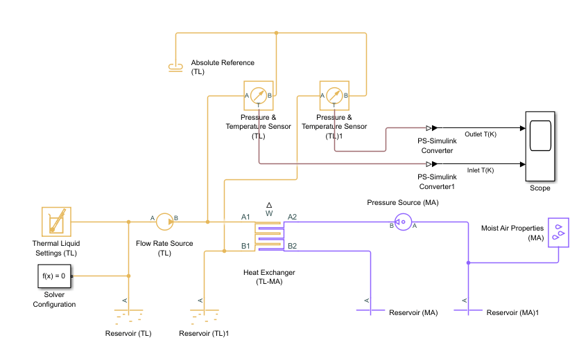
Create this model to test the radiator. This model simulates a thermal liquid at a constant temperature pumped at a constant flow rate through the radiator and a moist air at a constant temperature forced through the radiator at a constant pressure. The model measures the temperature difference between the inlet and outlet thermal fluids.

Create the above Simscape model by following these steps:
Add blocks shown in the diagram, and connect the blocks to the specified Heat Exchanger (TL-MA)
Specify the block parameters for these blocks:
Block Parameter Value Units Reservoir (TL) Reservoir temperature 350KCross-sectional area at port A liquid_pipe_Am^2Reservoir (TL)1 Reservoir temperature 293.15KCross-sectional area at port A liquid_pipe_Am^2Flow Rate Source (TL) Source type ConstantMass flow rate 0.1kg/sCross-sectional area at ports A and B liquid_pipe_Am^2Reservoir (MA) Cross-sectional area at port A
air_area_flowm^2Reservoir (MA)1 Cross-sectional area at port A
air_area_flowm^2Pressure Source (MA) Source type
ConstantPressure differential 0.0005MPaCross-sectional area at port A air_area_flowm^2Cross-sectional area at port B air_area_flowm^2On the Simulation tab, in the Simulate section, set Stop Time to
50.
On the Simulation tab, in the Simulate section, click Run. When the model finishes running, open the Scope block.

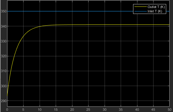
The blue and yellow curves indicate the temperatures of the inlet and outlet thermal
fluids. The steady state temperature of the outlet thermal fluid is 342
k, which indicates the radiator cools the thermal liquid by 8
k. Note that the initial temperature of the outlet thermal fluid equals
room temperature, which is 293.15 k.