Main Content

Tank (IL)

Tank in an isothermal liquid system

Since R2020a

  • Tank (IL) block

Libraries:
Simscape / Fluids / Isothermal Liquid / Tanks & Accumulators

Description

The Tank (IL) block models a container with up to six input ports, A through F, within an isothermal liquid system. The tank outputs fluid volume at port V and fluid level at port L as physical signals. The block models the hydrostatic pressure difference between the liquid surface and the inlet height level. The tank can be pressurized to a constant, user-specified value or to atmospheric pressure.

Fluid Volume

The volume of fluid in the tank is determined from the total mass flow into the tank:

V=Mρ,

where:

  • M is the total mass in the tank supplied by all ports.

  • ρ is the fluid density.

Due to the constant pressure in the tank, the liquid volume inside the tank changes based on mass flow rate. Note that the converse is true for pipes, where pressure is a function of fixed fluid volumes.

If the tank fluid volume exceeds the specified capacity of the tank, you can choose to be notified. Set the Liquid volume above max capacity parameter to Warning if you would like to receive a warning when this occurs during simulation. Set the parameter to Error if you would like the simulation to stop when this occurs.

Fluid Level

If Tank volume parameterization is set to Constant cross-section area, the fluid level in the tank is determined from the fluid volume V, due to the constant cross-sectional area of the tank. Otherwise, the fluid level can be specified as tabulated data in the Tabulated data - volume vs. level option.

When the level in the tank falls below the inlet height, the assumption that fluid entirely fills the volume of the connecting blocks may not be valid. Connections to a Pipe (IL) block, which is based on this assumption, may in this case return unphysical results. If you expect to model tank fluid levels below tank inlet height(s), connect the Tank (IL) block to your system with a 
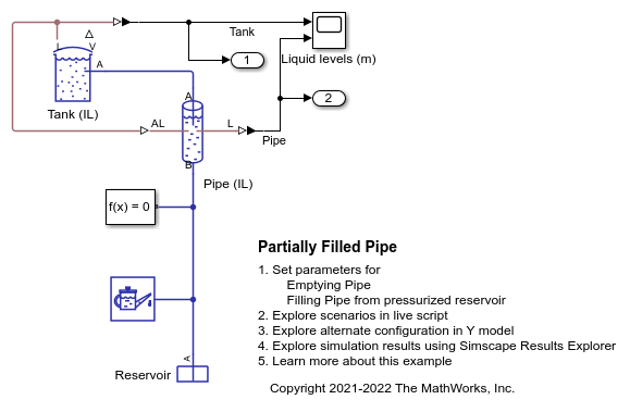
Partially Filled Pipe (IL) block instead.

Like the Liquid volume above max capacity parameter, you can be notified if the tank fluid level falls below the height of the inlet port(s) during your simulation by changing the Liquid level below inlet height parameter setting.

Mass Flow Rate

If you have more than one port enabled, the equations below apply to each port. The mass flow rate at the inlet port is:

m˙port=Aport2ρξΔpport[Δpport2+Δpport,crit2]1/4,

where:

  • Aport is the Inlet cross-sectional area.

  • ρ is the fluid density.

  • ζ is the Inlet pressure loss coefficient.

The inlet pressure difference due to inlet losses is:

Δpport=pport(P+Δpelev,port),

where:

  • pport is the pressure at the inlet port.

  • P is the Tank pressurization if the Pressurization specification parameter is set to Specified pressure. Otherwise, P is the atmospheric pressure.

  • Δpelev,port is the hydrostatic pressure difference at the specified port Inlet height: Δpelev,port=ρgL, where L is either the difference in height between the fluid level and the inlet height or zero, whichever is larger.

The critical pressure difference, Δpcrit, is the pressure differential associated with the critical Reynolds number, Recrit, which is the point of transition between laminar and turbulent flow in the fluid:

Δpcrit=πρPRloss8Aport(νRecrit)2,

where ν is the fluid kinematic viscosity.

Variables

To set the priority and initial target values for the block variables prior to simulation, use the Initial Targets section in the block dialog box or Property Inspector. For more information, see Set Priority and Initial Target for Block Variables.

Nominal values provide a way to specify the expected magnitude of a variable in a model. Using system scaling based on nominal values increases the simulation robustness. Nominal values can come from different sources, one of which is the Nominal Values section in the block dialog box or Property Inspector. For more information, see Modify Nominal Values for a Block Variable.

Ports

Conserving

expand all

Tank inlet.

Optional tank inlet.

Dependencies

To enable this port, set Number of inlets to 2, 3, 4, 5, or 6.

Optional tank inlet.

Dependencies

To enable this port, set Number of inlets to 3, 4, 5, or 6.

Optional tank inlet.

Dependencies

To enable this port, set Number of inlets to 4, 5, or 6.

Optional tank inlet.

Dependencies

To enable this port, set Number of inlets to 5 or 6.

Optional tank inlet.

Dependencies

To enable this port, set Number of inlets to 6.

Output

expand all

Liquid volume inside the tank in m^3, specified as a physical signal.

Liquid level inside the tank in m, specified as a physical signal.

Parameters

expand all

Number of inlet ports. Setting this parameter to 2 or more exposes additional input ports.

Specifies a constant tank pressure. You can define a non-atmospheric pressure by selecting Specified pressure and defining the value in Tank pressurization.

User-defined tank pressure.

Specifies tank area characteristics. This parameter is used to determine the fluid level in the tank. If you would like to model a tank with a variable cross-sectional area, you can provide data for tank volume and fluid level in the Tabulated data - volume vs. level option.

Tank cross-sectional area.

Dependencies

To enable this parameter, set Tank volume parameterization to Constant cross-section area.

Vector of tank fluid levels for the tabular parameterization of a non-constant tank area. The values in this vector correspond one-to-one to values in the Volumetric flow rate vector parameter. Its elements are listed in ascending order. The elements must be positive and the first element must be 0.

Dependencies

To enable this parameter, set Tank volume parameterization to Tabulated data - volume vs. level.

Vector of tank fluid volumes for the tabular parameterization of a non-constant tank area. The values in this vector correspond one-to-one to values in the Liquid level vector parameter. Its elements are listed in ascending order. The elements must be positive and the first element must be 0.

Dependencies

To enable this parameter, set Tank volume parameterization to Tabulated data - volume vs. level.

Height of inlet port. The value must be greater than or equal to 0.

Dependencies

To enable this parameter, set Number of inlets to 1.

Cross-sectional area of the port inlet. This value must be greater than 0.

Loss coefficient for pressure at inlet port. This value is used for calculating the hydrostatic pressure at the inlet and determining the fluid level minimum conditions.

Vector of port heights for multiple enabled ports. If you have two or more ports enabled, the Inlet height parameter becomes a vector of values that correspond to the height of each inlet port, starting with port A. The parameter name and vector length depend on the value of the Number of inlets parameter. The default height for each inlet is .1 m. Each element of this vector must be greater than or equal to 0.

Dependencies

To enable this parameter, set Number of inlets to 2, 3, 4, 5, or 6.

Vector of cross-sectional areas for multiple enabled ports. If you have two or more ports enabled, the Inlet cross-sectional area parameter becomes a vector of values that correspond to the cross-sectional area of each inlet, starting with port A. The parameter name will include all enabled ports. Each element of this vector must be greater than 0.

Dependencies

To enable this parameter, set Number of inlets to 2, 3, 4, 5, or 6.

Vector of pressure loss coefficients for multiple enabled ports. If you have two or more ports enabled, the Pressure loss coefficient parameter becomes a vector of values corresponding to the loss coefficient for each inlet port, starting with port A. The parameter name will include all enabled ports. Each element of this vector must be greater than 0.

Dependencies

To enable this parameter, set Number of inlets to 2, 3, 4, 5, or 6.

Whether to be notified if the tank fluid level falls below the port inlet height during simulation. Set this parameter to Warning if you would like to receive a warning when this occurs during simulation. Set the parameter to Error if you would like the simulation to stop when this occurs.

Whether to be notified if the tank fluid volume rises above the tank maximum capacity during simulation. Set this parameter to Warning if you would like to receive a warning when this occurs during simulation. Set the parameter to Error if you would like the simulation to stop when this occurs.

Fill limit of the tank.

Dependencies

To enable this parameter, set Liquid volume above max capacity to either:

  • Warning

  • Error

Constant for the acceleration of gravity.

Extended Capabilities

C/C++ Code Generation
Generate C and C++ code using Simulink® Coder™.

Version History

Introduced in R2020a