Main Content

Specific Dissipation Heat Exchanger (G)

R2026b

Heat exchanger parameterized by specific dissipation data for systems with gas and controlled flows

Since R2024a

  • Heat Exchanger (G) block

Libraries:
Simscape / Fluids / Heat Exchangers / Gas

Description

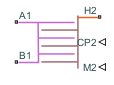
The Specific Dissipation Heat Exchanger (G) block models heat exchange between a gas, which flows between ports A1 and B1, and an external, controlled fluid via a physical signal.
Heat Transfer Model

The block heat transfer model depends on the concept of specific dissipation, a measure of the heat transfer rate observed when gas and controlled fluid inlet temperatures differ by one degree. Its product with the inlet temperature difference gives the expected heat transfer rate:

Q=ξ(TIn,1−TIn,2),

where ξ is specific dissipation and TIn is inlet temperature for gas (subscript 1) or controlled fluid (subscript 2). The specific dissipation is a tabulated function of the mass flow rates into the exchanger through the gas and controlled fluid inlets:

ξ=f(m˙1,m˙2)

To accommodate reverse flows, the tabulated data can extend over positive and negative flow rates, in which case the inlets can also be thought of as outlets.

The specific dissipation is the heat exchanger heat transfer rate divided by the difference in inlet temperatures

ξ=QTIn,1−TIn,2.

The specific dissipation is also equal to the overall heat transfer coefficient defined based on inlet temperature multiplied by the heat transfer surface area or the heat capacity rate multiplied by the effectiveness factor, for whichever fluid has a smaller value.

The heat transfer model, as it relies almost entirely on tabulated data, and as that data normally derives from experiment, requires little detail about the exchanger. Flow arrangement, mixing condition, and number of shell or tube passes, if relevant to the heat exchanger modeled, are assumed to manifest entirely in the tabulated data.

The fluid properties that the block uses in heat transfer calculations are the average between the value at the inlet and the value in the fluid volume.

Composite Structure

The block is a composite component. A Specific Dissipation Heat Exchanger Interface (G) block models the gas flow. Physical signals for the heat transfer coefficient and mass flow rate, along with a thermal port for temperature, capture the controlled flow. A Specific Dissipation Heat Transfer block models the heat exchanged across the wall between the flows.

Ports

Conserving

expand all

Opening for gas to enter and exit its side of the heat exchanger.

Programmatic Use

Port: A1

Opening for gas to enter and exit its side of the heat exchanger.

Programmatic Use

Port: B1

Entrance temperature of controlled fluid 2.

Programmatic Use

Port: H2

Input

expand all

Instantaneous value of the isobaric specific heat for the controlled fluid.

Programmatic Use

Port: CP2

Instantaneous value of the mass flow rate of the controlled fluid.

Programmatic Use

Port: M2

Output

expand all

Rate of heat transfer to the gas, in W.

Programmatic Use

Port: Q1

Parameters

expand all

Heat Transfer

Mass flow rate of gas at each breakpoint in the lookup table for the specific heat dissipation table. The block inter- and extrapolates the breakpoints to obtain the specific heat dissipation of the heat exchanger at any mass flow rate. Interpolation is linear and extrapolation is nearest.

The mass flow rates can be positive, zero, or negative, but they must increase monotonically from left to right. Their number must equal the number of columns in the Specific heat dissipation table parameter. If the table has m rows and n columns, the mass flow rate vector must be n elements long.

Programmatic Use

Parameter: mdot1_TLU

Mass flow rate of controlled fluid at each breakpoint in the lookup table for the specific heat dissipation table. The block inter- and extrapolates the breakpoints to obtain the specific heat dissipation of the heat exchanger at any mass flow rate. Interpolation is linear and extrapolation is nearest.

The mass flow rates can be positive, zero, or negative, but they must increase monotonically from left to right. Their number must equal the number of columns in the Specific heat dissipation table parameter. If the table has m rows and n columns, the mass flow rate vector must be n elements long.

Programmatic Use

Parameter: mdot2_TLU

Specific heat dissipation at each breakpoint in its lookup table over the mass flow rates of gas and controlled fluid. The block inter- and extrapolates the breakpoints to obtain the effectiveness at any pair of gas and controlled fluid mass flow rates. Interpolation is linear and extrapolation is nearest.

The specific heat dissipation values must be not be negative. They must align from top to bottom in order of increasing mass flow rate in the gas channel, and from left to right in order of increasing mass flow rate in the controlled fluid channel. The number of rows must equal the size of the Gas mass flow rate vector parameter, and the number of columns must equal the size of the Controlled fluid mass flow rate vector parameter.

If your heat exchanger data sheet supplies the heat transfer coefficients, multiply the provided heat transfer coefficients by the surface area to calculate the specific dissipation.

Programmatic Use

Parameter: SD_TLU

Warning condition for specific heat dissipation in excess of minimum heat capacity rate. Heat capacity rate is the product of mass flow rate and specific heat, and its minimum value is the lowest between the flows. This minimum gives the specific dissipation for a heat exchanger with maximum effectiveness and cannot be exceeded. See the Specific Dissipation Heat Transfer block for more detail.

Programmatic Use

Parameter: Q_check
Values: "simscape.enum.assert.action.warn" | "simscape.enum.assert.action.none" | "simscape.enum.assert.action.error"

Pressure Loss

Mass flow rate at each breakpoint in the lookup table for the pressure drop. The block inter- and extrapolates the breakpoints to obtain the pressure drop at any mass flow rate. Interpolation is linear and extrapolation is nearest.

The mass flow rates can be positive, zero, or negative and they can span across laminar, transient, and turbulent zones. They must, however, increase monotonically from left to right. Their number must equal the size of the Pressure drop vector parameter, with which they are to combine to complete the tabulated breakpoints.

Programmatic Use

Parameter: mdot_dp_TLU_1

Parameter: mdot_dp_TLU_2

Pressure drop at each breakpoint in its lookup table over the mass flow rate. The block inter- and extrapolates the breakpoints to obtain the pressure drop at any mass flow rate. Interpolation is linear and extrapolation is nearest.

The pressure drops can be positive, zero, or negative, and they can span across laminar, transient, and turbulent zones. They must, however, increase monotonically from left to right. Their number must equal the size of the Mass flow rate vector parameter, with which they are to combine to complete the tabulated breakpoints.

Programmatic Use

Parameter: p_diff_TLU_1

Parameter: p_diff_TLU_2

Absolute temperature established at the inlet in the gathering of the tabulated pressure drops. The reference inflow temperature and pressure determine the fluid density assumed in the tabulated data. During simulation, the ratio of reference to actual fluid densities multiplies the tabulated pressure drop to obtain the actual pressure drop.

Programmatic Use

Parameter: T_ref_in_1

Parameter: T_ref_in_2

Absolute pressure established at the inlet in the gathering of the tabulated pressure drops. The reference inflow temperature and pressure determine the fluid density assumed in the tabulated data. During simulation, the ratio of reference to actual fluid densities multiplies the tabulated pressure drop to obtain the actual pressure drop.

Programmatic Use

Parameter: p_ref_in_1

Parameter: p_ref_in_2

Mass flow rate below which its value is numerically smoothed to avoid discontinuities known to produce simulation errors at zero flow. See the Specific Dissipation Heat Exchanger Interface (G) block for detail on the calculations for the gas side of the exchanger.

Programmatic Use

Parameter: mdot_threshold_1

Parameter: mdot_threshold_2

Volume of fluid in the gas flow channel.

Programmatic Use

Parameter: gas_volume_1

Flow area at the inlet and outlet of the gas flow channel. The ports are of the same size.

Programmatic Use

Parameter: area_1

Effects and Initial Conditions

Option to model the pressure dynamics in the gas channel. If you clear this checkbox, the block removes the pressure derivative terms from the component energy and mass conservation equations.

Programmatic Use

Parameter: dynamic_compressibility_1
Values: "true" | "false"

Gas temperature at nominal operating conditions. The block uses this value to calculate the nominal density to use in the mass and energy conservation equation when dynamic compressibility is disabled.

Dependencies

To enable this parameter, clear the Enable Gas dynamic compressibility checkbox.

Programmatic Use

Parameter: T_nominal_1

Gas pressure at nominal operating conditions. The block uses this value to calculate the nominal density to use in the mass and energy conservation equation when dynamic compressibility is disabled.

Dependencies

To enable this parameter, clear the Enable Gas dynamic compressibility checkbox.

Programmatic Use

Parameter: p_nominal_1

Temperature in the gas channel at the start of simulation.

Programmatic Use

Parameter: T0_1

Pressure in the gas channel at the start of simulation.

Dependencies

To enable this parameter, select Enable Gas dynamic compressibility.

Programmatic Use

Parameter: p0_1

Extended Capabilities

expand all

C/C++ Code Generation
Generate C and C++ code using Simulink® Coder™.

Version History

Introduced in R2024a

expand all